
Exhaled gas measurement compensation during high flow respiratory therapy

a technology of respiratory therapy and compensation, which is applied in the field of respiratory therapy, can solve the problems of difficult to conduct patient condition assessment, incorrect diagnosis or assumption of disease conditions, and non-uniform distribution of gas from the alveoli to the nose and mouth

Pending Publication Date: 2020-12-10
FISHER & PAYKEL HEALTHCARE LTD
View PDF15 Cites 2 Cited by
  • Summary
  • Abstract
  • Description
  • Claims
  • Application Information

AI Technical Summary

Benefits of technology

Enables accurate estimation of exhaled gas concentrations, reducing errors and improving diagnostic accuracy by accounting for dilution effects caused by high flow respiratory therapy, allowing for reliable monitoring of patient respiratory status.

Problems solved by technology

When gas measurements, such as capnography, are used in conjunction with non-sealed respiratory flow systems, assessments of patient condition are difficult to conduct due to the flushing mechanism of the flow therapy.
The flows delivered to the patient flush the dead space in the upper airways resulting in a non-uniform distribution of gas from the alveoli to the nose and mouth.
This can lead to an incorrect diagnosis or assumptions about disease conditions.
The ETCO2, or any other measurement of exhaled gases, measured during high flow therapy tends to incorrectly estimate the concentration, and this incorrect estimation increases in magnitude with increasing flow rate.
For example, a healthy individual who receives high flow respiratory therapy at 30 L / min can have reported ETCO2 that is 50% lower, and more preferably lower than 80%, of its actual value, resulting in inaccurate assessments.
The same is true for any other non-sealed respiratory flow therapies where gas is allowed to escape making measurements of exhaled gas difficult.

Method used


Image

  • Exhaled gas measurement compensation during high flow respiratory therapy
  • Exhaled gas measurement compensation during high flow respiratory therapy
  • Exhaled gas measurement compensation during high flow respiratory therapy

Examples


Embodiment Construction

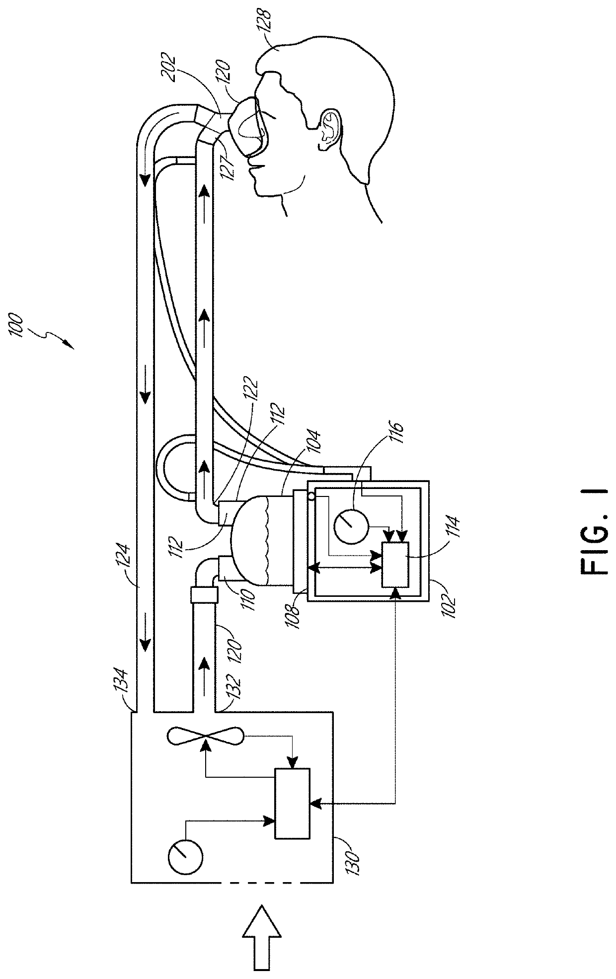
[0066]Although certain embodiments and examples are described below, those of skill in the art will appreciate that the disclosure extends beyond the specifically disclosed embodiments and / or uses and obvious modifications and equivalents thereof. Thus, it is intended that the scope of the present disclosure should not be limited by any particular embodiments described below.

[0067]In some configurations, the gas supply is configured to supply gas to the humidifier at a flow rate between about 5 liters per minute and about 120 liters per minute.

[0068]As relatively high gas delivery flow rates may be used with the embodiments or configurations described herein, the gases being supplied or delivered to the user or patient can may be delivered to different parts of the user's or a patient's airway. The gases being supplied may reach the patient's lungs or any part of the respiratory system.

[0069]For example, according to those various embodiments and configurations described herein, a f...


PUM


Abstract

The present disclosure relates to determining a corrected exhaled gas measurement during high flow respiratory therapy. Measuring exhaled gas concentration during high flow respiratory therapy is difficult and inaccurate due to a phenomenon known as flushing. The high flows delivered to the patient flush the dead space in the conducting airways, which causes a dilution effect that results in underestimated or overestimated exhaled gas measurement depending on the gas composition delivered by the high flow system. This can lead to incorrect clinical measurements and diagnoses. Various algorithms are disclosed herein to account for the dilution effect caused by flushing, allowing for the method of measuring gas concentrations to still be used accurately for clinical measurements.

Description

INCORPORATION BY REFERENCE TO ANY PRIORITY APPLICATIONS[0001]This application is a continuation of U.S. application Ser. No. 15 / 508,703, filed Mar. 3, 2017, titled “EXHALED GAS MEASUREMENT COMPENSATION DURING HIGH FLOW RESPIRATORY THERAPY,” which is a national phase entry of PCT Application No. PCT / IB2015 / 056729, filed Sep. 4, 2015, titled “EXHALED GAS MEASUREMENT COMPENSATION DURING HIGH FLOW RESPIRATORY THERAPY,” which is claims the priority benefit of U.S. Provisional Application No. 62 / 046,052, filed Sep. 4, 2014, the entirety of which is hereby incorporated by reference herein. Any and all applications for which a foreign or domestic priority claim is identified in the Application Data Sheet as filed with the present application are hereby incorporated by reference under 37 CFR 1.57.[0002]In addition, the applications listed on the following chart are specifically incorporated herein in their entireties by reference.Attorney DocketFilingapplicationNo.DateTitleSer. No.FPHCR.387P...

Claims


Application Information

Patent Timeline
Patent Type & Authority Applications(United States)
IPC IPC(8): A61B5/083A61M16/00A61M16/08A61B5/091A61M16/06
CPCA61M16/0069A61M2016/0027A61M2016/0042A61B5/0836A61M16/0666A61M2230/432A61M16/085A61B5/091A61M2016/102A61M2230/435A61M16/0051A61M16/0883A61M16/06A61M16/0096A61M2205/3334
Inventor EVANS, ALICIA JERRAM HUNTERSPENCE, CALLUM JAMES THOMASWHITE, CRAIG KARLKEOGH, GERALDINEPAYTON, MATTHEW JONGULLIVER, LAURENCEASSI, MILANJOT SINGHOLDFIELD, SAMANTHA DALEHERMEZ, LAITH ADEEB
Owner FISHER & PAYKEL HEALTHCARE LTD
Learn More