Blood circulation system

a blood circulation system and blood flow technology, applied in the field of blood circulation systems, can solve the problems of complex and advanced operation techniques, and achieve the effects of stably transferring blood, efficiently circulating blood, and efficiently adjusting the blood transfer ra

Pending Publication Date: 2020-12-10
SENKO MED INSTR MFG CO LTD
View PDF0 Cites 0 Cited by
  • Summary
  • Abstract
  • Description
  • Claims
  • Application Information

AI Technical Summary

Benefits of technology

[0047]The blood circulation system of the invention is capable of stably transferring blood and efficiently circulating blood.
[0048]Since it is possible to adjust the blood transfer rate from an arbitrary circumferential position of the encoder, in a case where the linked control is not continuously performed, and the blood transfer control transitions to the normal control, it is possible to adjust the blood transfer rate with respect to a circumferential position after the blood transfer control transitions to the normal control. Accordingly, the blood circulation system is capable of efficiently adjusting the blood transfer rate in the normal control without stopping.
[0049]In a case where the blood transfer rate in the linked control is significantly smaller than a blood transfer rate that is set by the blood transfer rate adjustment unit in the normal control before the blood transfer control transitions to the linked control, it is possible to prevent blood from being transferred at the previously set blood transfer rate, after the blood transfer control transitions to the normal control, and it is possible to stably circulate blood.

Problems solved by technology

Since the clinical engineer adjusts the amount of discharge of the blood transfer pump by manually controlling the rotational speed of the blood transfer pump (roller pump, centrifugal pump, or the like) when adjusting the blood flow rate, a complex and advanced operation technique is required in addition to the adjustment of each line.

Method used


Image

  • Blood circulation system
  • Blood circulation system
  • Blood circulation system

Examples


first embodiment

[0062]Hereinafter, an artificial heart and lung apparatus (blood circulation system) of a first embodiment of the present invention will be described with reference to FIGS. 1 to 6.

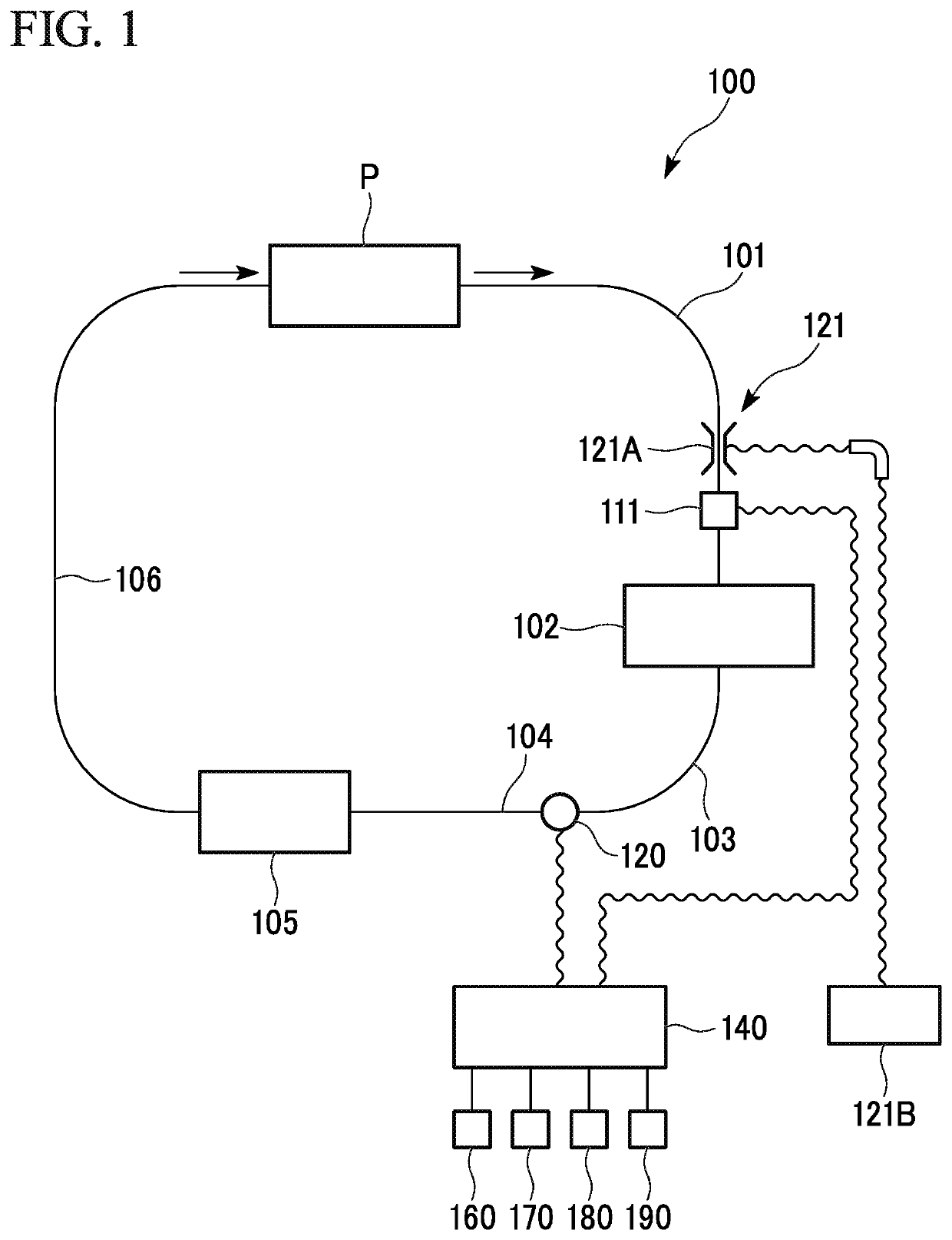
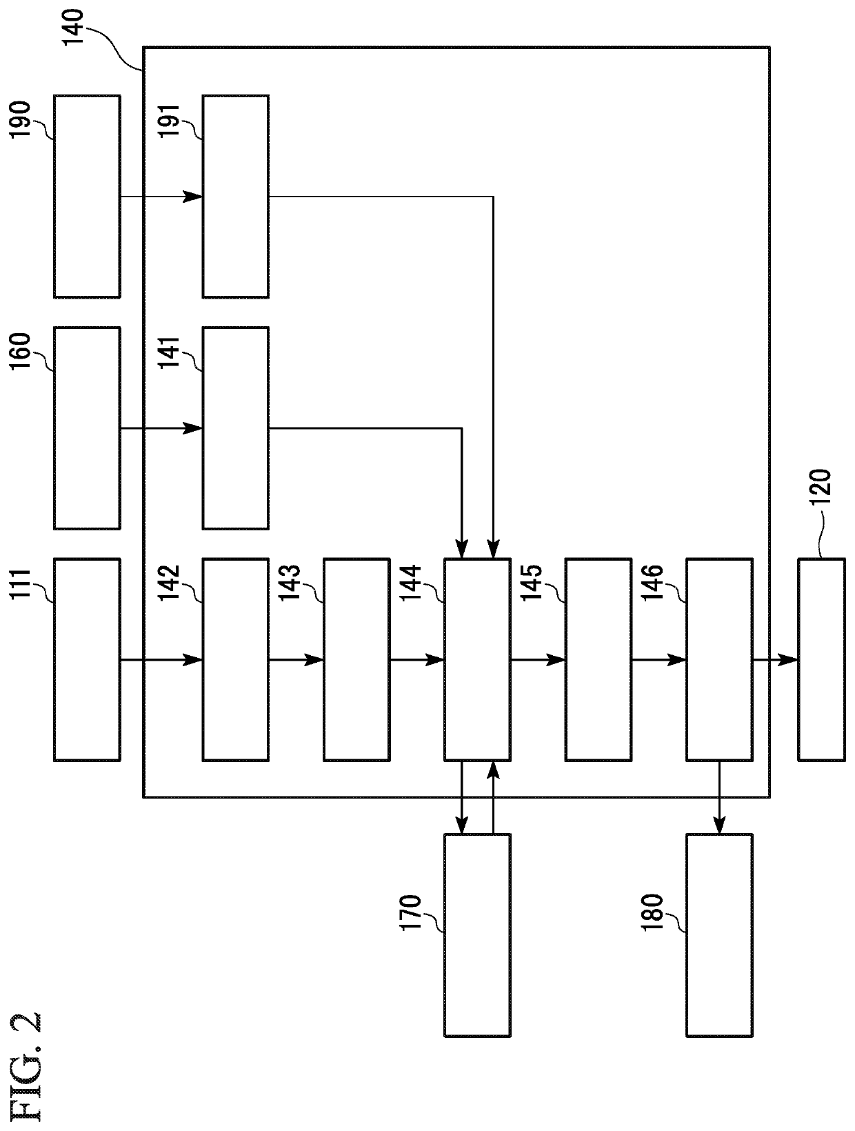
[0063]FIG. 1 is a circuit diagram showing a schematic configuration of the artificial heart and lung apparatus of the first embodiment of the present invention. Reference sign 100 represents an artificial heart and lung apparatus, a reference sign 111 represents a blood removal rate sensor, reference sign 120 represents a roller pump, a reference sign 140 represents a controller, a reference sign 160 represents a blood transfer rate adjustment unit (blood transfer rate instruction means), and a reference sign 170 represents a linked blood transfer rate storage.

[0064]As shown in FIG. 1, the artificial heart and lung apparatus 100 includes a blood removal line 101; a reservoir 102; a blood line 103; a first blood transfer line (blood transfer line) 104; an artificial lung 105; a second blood transfer line (...

second embodiment

[0163]Hereinafter, an artificial heart and lung apparatus (blood circulation system) of a second embodiment of the present invention will be described with reference to FIGS. 7 to 11.

[0164]FIG. 7 is a circuit diagram showing a schematic configuration of the artificial heart and lung apparatus of the second embodiment. Reference sign 200 represents an artificial heart and lung apparatus, reference sign 112 represents a blood transfer rate sensor (blood transfer rate measurement means), reference sign 220 represents a centrifugal pump (blood transfer pump), and reference sign 240 represents a controller.

[0165]As shown in FIG. 7, an artificial heart and lung apparatus 200 includes the blood removal line 101; the reservoir 102; the blood line 103; a centrifugal pump 220; the first blood transfer line (blood transfer line) 104; the artificial lung 105; the second blood transfer line (blood transfer line) 106; the blood removal rate sensor 111; a blood transfer rate sensor 112; the blood ...


PUM


Abstract

An artificial heart and lung apparatus (100) includes a roller pump (120); a blood removal line (101); a first blood transfer line (104); a blood removal rate sensor (111); a control unit (140) that performs the linked control of the roller pump (120) in correspondence with a blood removal rate; and a blood transfer rate adjustment unit (160) that instructs the roller pump (120) to transfer a blood transfer rate. The blood transfer rate adjustment unit (160) includes an operation amount input unit to which an operation amount from an arbitrary circumferential position can be input, and which outputs a pulse signal according to the input operation amount, and a counter that adds and subtracts pulse signals output from the operation amount input unit, and outputs a resultant as blood transfer rate adjustment data, and the counter performs a counting operation with respect to the circumferential position of the operation amount input unit when blood transfer control transitions to the normal control.

Description

CROSS-REFERENCE TO RELATED APPLICATION(S)[0001]This application claims the benefit of U.S. patent application Ser. No. 15 / 502,091, filed Feb. 6, 2017, which is a U.S. National Stage entry of PCT Application No. PCT / JP2015 / 073425, filed on Aug. 20, 2015, which priority is claimed on Japanese Patent Application No. 2014-167559, filed Aug. 20, 2014, Japanese Patent Application No. 2015-053600, filed Mar. 17, 2015, and Japanese Patent Application No. 2015-114037, filed Jun. 4, 2015, the disclosure of which is hereby incorporated by reference in its entirety.TECHNICAL FIELD[0002]The present invention relates to a blood circulation system that circulates removed blood via a blood transfer pump.[0003]Priority is claimed on Japanese Patent Application No. 2014-167559, filed Aug. 20, 2014, Japanese Patent Application No. 2015-53600, filed Mar. 17, 2015, and Japanese Patent Application No. 2015-114037, filed Jun. 4, 2015, the contents of which are incorporated herein by reference.BACKGROUND A...

Claims


Application Information

Patent Timeline
Patent Type & Authority Applications(United States)
IPC IPC(8): A61M1/36A61M1/38
CPCA61M2205/3334A61M1/3607A61M1/38A61M1/3666A61M2205/3365A61M1/3623
Inventor NIIMI, YOSHINARITANAKA, KATSUNORIKIHARA, MASAHIROKISHI, MUNEHIROMARUYA, TAKUYOSHIHARA, MASANORIKAMIYA, MASAHIRO
Owner SENKO MED INSTR MFG CO LTD
Why Eureka
Try Eureka