
Self-aligning to wind facing floating platform supporting multi-wind turbines and solar for wind and solar power generation and the construction method thereon

a technology of wind and solar power generation and floating platform, which is applied in the direction of special purpose vessels, vessel construction, greenhouse gas reduction, etc., can solve the problems of high construction cost, huge electricity consumption of offshore wind power generation, and lack of offshore wind power development behind land-based wind power developmen

Active Publication Date: 2020-12-17
WONG CARLOS +1
View PDF0 Cites 6 Cited by
  • Summary
  • Abstract
  • Description
  • Claims
  • Application Information

AI Technical Summary

Benefits of technology

This patent describes a platform for wind power generation that can align itself to the wind and support multiple wind turbines. The platform includes three or more floaters and three or more connection beams that connect the floaters together. This design allows for self-alignment and reduces the impact of wind loads on the turbines, resulting in increased efficiency and stability of the platform. Additionally, the patent describes different embodiments of the platform that vary in the number and orientation of the wind turbines, as well as the use of a rotation axle to restrain the platform from drifting away. The technical effects of this design include improved wind power generation and reduced costs associated with maintenance and repair of wind turbines.

Problems solved by technology

The world's metropolitan cities are all close to the shore and their electricity consumption are huge.
However, offshore wind power development has been lacking behind land-based wind power development.
This is due primarily to the high construction costs of the turbine bottom which is fixed to a foundation in sea.
The bottom fixed type wind turbine is only effective in the shallow near shore waters due to the construction difficulty in deep water.
Large scale special piling vessels are required for sinking the large diameter steel piles; as such, these vessels are quite expensive and usually are controlled by only a few companies.
In this situation, the bottom fixed-type wind turbine is uneconomical, however, the floating type is a more attractive alternative.
To support a structure of several hundred tons (including power generator, gear box, yaw mechanism and the rotor blades integral located at a height of 100 m at the tip of the tower) supporting such a structure on a floating body makes it extremely difficult to control its stability.
This is too difficult to meet for a single floating turbine, because the floater base dimension is small as compared to the tower height, which is at least twice that of the base diameter.
The moment of inertia of the base is therefore inadequate to control rolling and pitching movements of the floating platform.
The wake effects cause the potential power loss of the downwind turbines as well as imposing fatigue loads on the downwind turbines.
If the spacing is maintained too short, the loss from the wake effect will be large.
Additionally, for a modern large-scale wind turbine, the rotor diameter of the turbine is typically over 50 m. In this case, the diameter could be at least 300 m to 500 m. Moreover, as there is also an underwater cable of great length linking the turbines together, the resistance of this long underwater cable will cause loss in power transmission.
The platform base is small in comparison with the tower height; therefore, the problem of stability of the platform, together with wind wake loss, remain un-resolved.
Since this triangular tubular structure is very large, the swindling around one corner will produce a very large sweeping area which may post a danger to other marine users.

Method used


Image

  • Self-aligning to wind facing floating platform supporting multi-wind turbines and solar for wind and solar power generation and the construction method thereon
  • Self-aligning to wind facing floating platform supporting multi-wind turbines and solar for wind and solar power generation and the construction method thereon
  • Self-aligning to wind facing floating platform supporting multi-wind turbines and solar for wind and solar power generation and the construction method thereon

Examples


Embodiment Construction

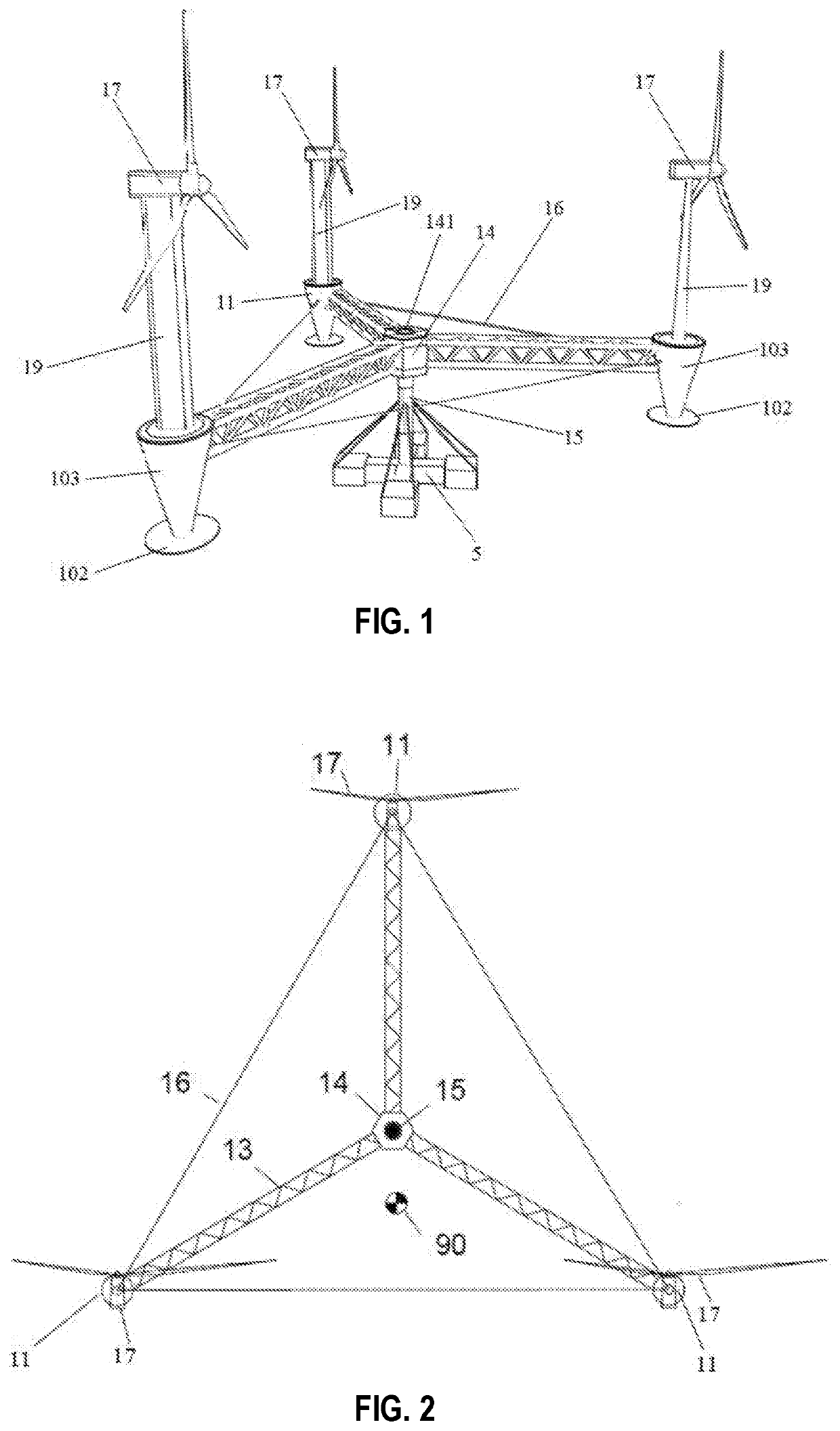
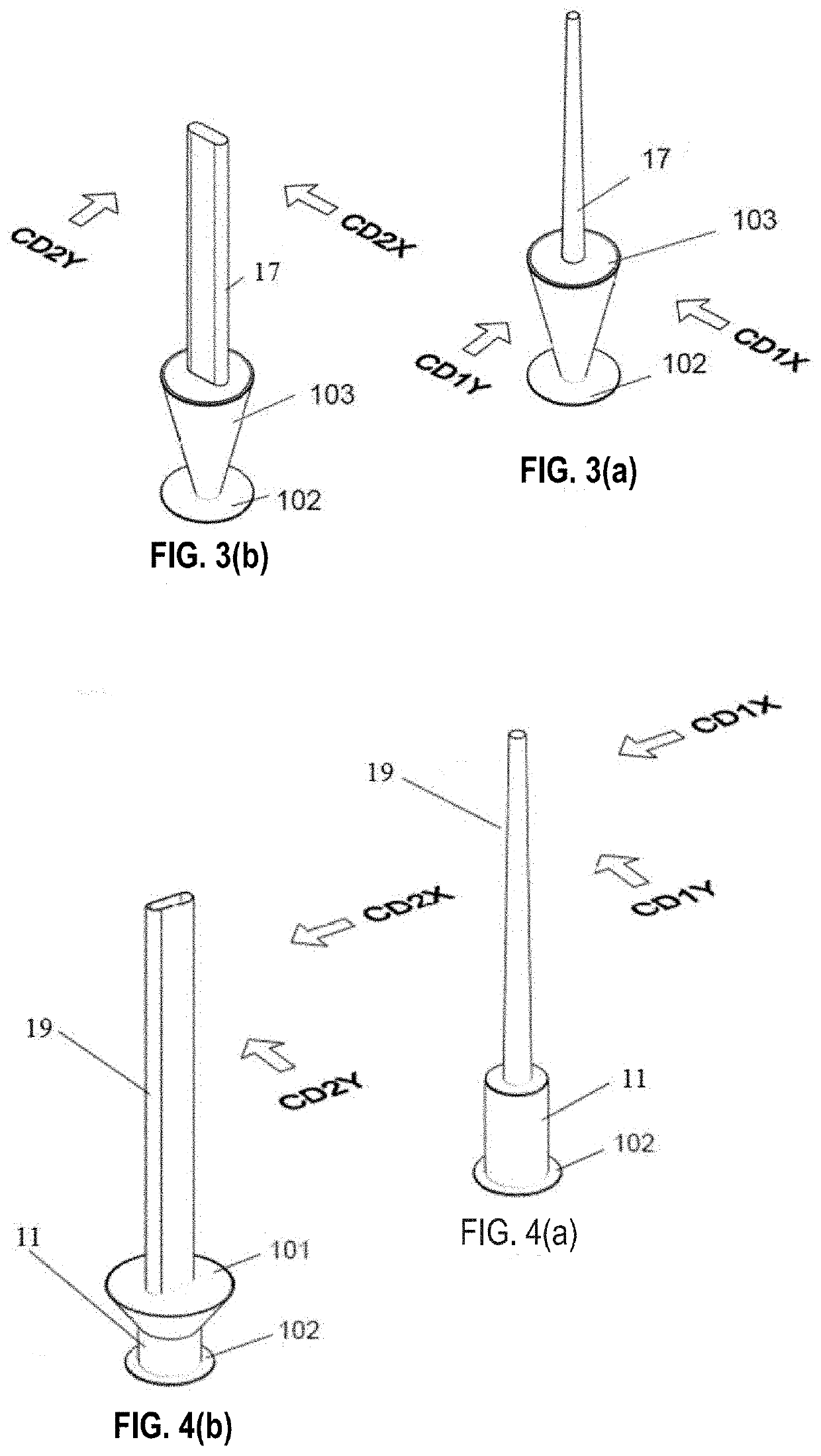
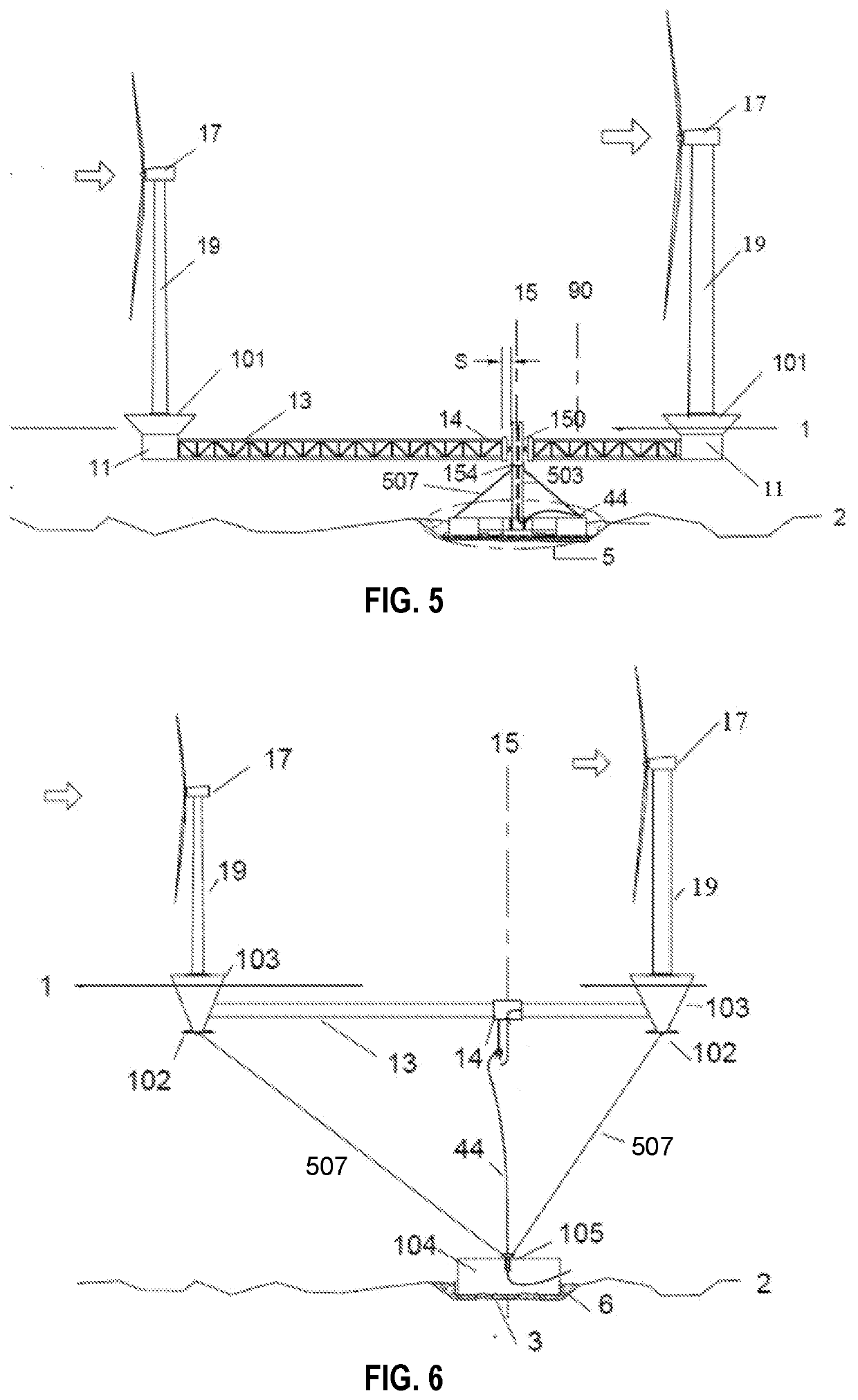
[0046]As used herein, the term “floater” refers to a floating structure in a body of water on which a wind power turbine may be mounted thereon. As used herein, the phrase “self-aligning to wind” means that the turbine rotor blades' rotating surface is perpendicular to the incoming wind. Additionally as used herein, the term “wind tracing” means a turbine turning to the designated direction following the change of the wind direction. Hereafter, the center of gravity or “C.G.” means the center of gravity of any mass in the described subject matter. Further, the center of geometry or “C.Geo.” means the center of geometry of the wind load receiving areas for the described subject matter.

[0047]The example embodiments to be more fully described hereafter are directed to a self-aligning to wind floating platform supporting multiple wind turbines for wind power generation, the platform adapted to be deposited in a body of water to generate electricity, as well as the platform's application...


PUM


Abstract

A self-aligning to the incoming wind floating platform supporting multiple wind turbines (17, 18) forms a wind power generation unit. Under horizontal wind, the wind load resultant passes the center of geometry (or “C.Geo”) of the wind load receiving areas of the floating platform, but not the turning axis (15). This results in a yaw moment about the turning axis (15) to turn the floating platform, until the wind load resultant simultaneously passes through the C.Geo and the turning axis (15). A wind park or wind farm may include at least one of these floating platforms that are capable of self-aligning to the incoming wind for electric power generation. The floating platform helps reduce the length of a submarine power cable (44) of the platform, hence reducing electric resistance and subsequently heat loss, thereby reducing the cost of the submarine power cable (44).

Description

CROSS-REFERENCE TO RELATED APPLICATIONS[0001]The present application claims the benefit under 35 U.S.C. § 363, § 365(c) and § 120 of PCT International Application Serial No. PCT / IB2018 / 059317 to co-applicants ZHUHAI KALOUSI (MACAU) ENGINEERING CONSULTANT LTD. and Carlos WONG, filed Nov. 26, 2018, pending, which in turn claims priority to pending Chinese Pat. Appl. Ser. No. 201711187761.2, filed Nov. 24, 2017. The entire contents of each application is hereby incorporated by reference herein.BACKGROUND1. Field[0002]Example embodiments in general relate to a self-aligning to wind floating platform supporting multiple wind turbines for wind power generation deposited in a body of water to generate electricity, its application in offshore wind farm power installation, and the fabrication and construction method thereon.2. Related Art[0003]The world's metropolitan cities are all close to the shore and their electricity consumption are huge. Offshore wind power is the most suitable green ...

Claims


Application Information

Patent Timeline
Patent Type & Authority Applications(United States)
IPC IPC(8): F03D13/25B63B35/44
CPCF05B2240/95F05B2240/93B63B21/50B63B35/44B63B2035/446F03D13/25F03D1/02F03D7/0204B63B35/4406Y02E70/30B63B75/00
Inventor WONG, CARLOS
Owner WONG CARLOS
Learn More