Planar solar concentrator power module

a solar concentrator and power module technology, applied in solar heat systems, pv power plants, light and heating equipment, etc., can solve the problems of low cost thin film cells, high cost of silicon wafers, and high cost of solar cells to compete with electric power companies. , to achieve the effect of low cost, labor-intensive and easy handling

Inactive Publication Date: 2008-06-17
JX CRYSTALS
View PDF62 Cites 136 Cited by
  • Summary
  • Abstract
  • Description
  • Claims
  • Application Information

AI Technical Summary

Benefits of technology

[0012]The conventional planar modules consist of large silicon cells sandwiched between plastic sheets with a glass front plate surrounded by a 2″ thick metal frame, for example aluminum frame, for rigidity. Our preferred planar concentrator solar module consists of a back metal sheet upon which linear silicon cell circuits are mounted. In the embodiment depicted, there are plural circuits, as for example but not limited to, 6 circuits containing cells approximately 1.3″ or 1.2″ wide. The circuit separation is, for example, 4″ or 3.6″. Therefore, the cell area represents one third of the total module area resulting in a major cost reduction for cells.
[0031]15. The fact that this unit resembles a traditional planar solar module will lead to easy customer acceptance. Thereafter, it would lead to an even more lower cost, higher concentration ratio systems.

Problems solved by technology

Solar cells generate electricity but at a cost which is too high to compete with electricity from the electric power company.
The second approach is based on the assumption that the cost of silicon wafers is too high and one needs to make low cost thin film cells.
The problem with this approach has been that destroying the crystal material degrades solar cell performance.
To date, this approach has not yielded modules costing less than $8 per Watt.
However, the problems with this approach are not technical but instead relate to business and politics.
The problem here is not with the technology.
The problem here is that the investment required to create positive cash flow is too large.
Large companies will not take the risk and small companies do not have the resources and the government is not helping.
Furthermore, trackers with the required accuracy are not being manufactured.
Finally, these systems are not cost effective unless made in large sizes and in large volumes and there are no intermediate markets other than the utility scale market.
This is also a technically proven approach but this approach also suffers from the investment problem.
However, this presents two problems.
The first problem is that the planar cells have to be significantly modified to operate at 20 suns.
The second problem is that the planar cell suppliers are not motivated to cooperate.
For example, suppose that the concentrator approach proves to be cheaper and the market expands by three times. The problem for the planar cell suppliers is that their part will actually shrink by 3 / 20 times. Again, these systems are not cost effective unless made in large sizes and in large volumes and there are no intermediate markets other than the utility scale market.
Unfortunately, this approach was technically naive.
The problem encountered was that the modules then absorbed 1.5 times more energy and there was no provision to remove the additional heat.
This then affected the module lifetime.
The investment required for manufacturing scale-up versions of a new cell is prohibitive.
Another problem that needs to be solved is the cell-interconnect problem.

Method used


Image

  • Planar solar concentrator power module
  • Planar solar concentrator power module
  • Planar solar concentrator power module

Examples


Embodiment Construction

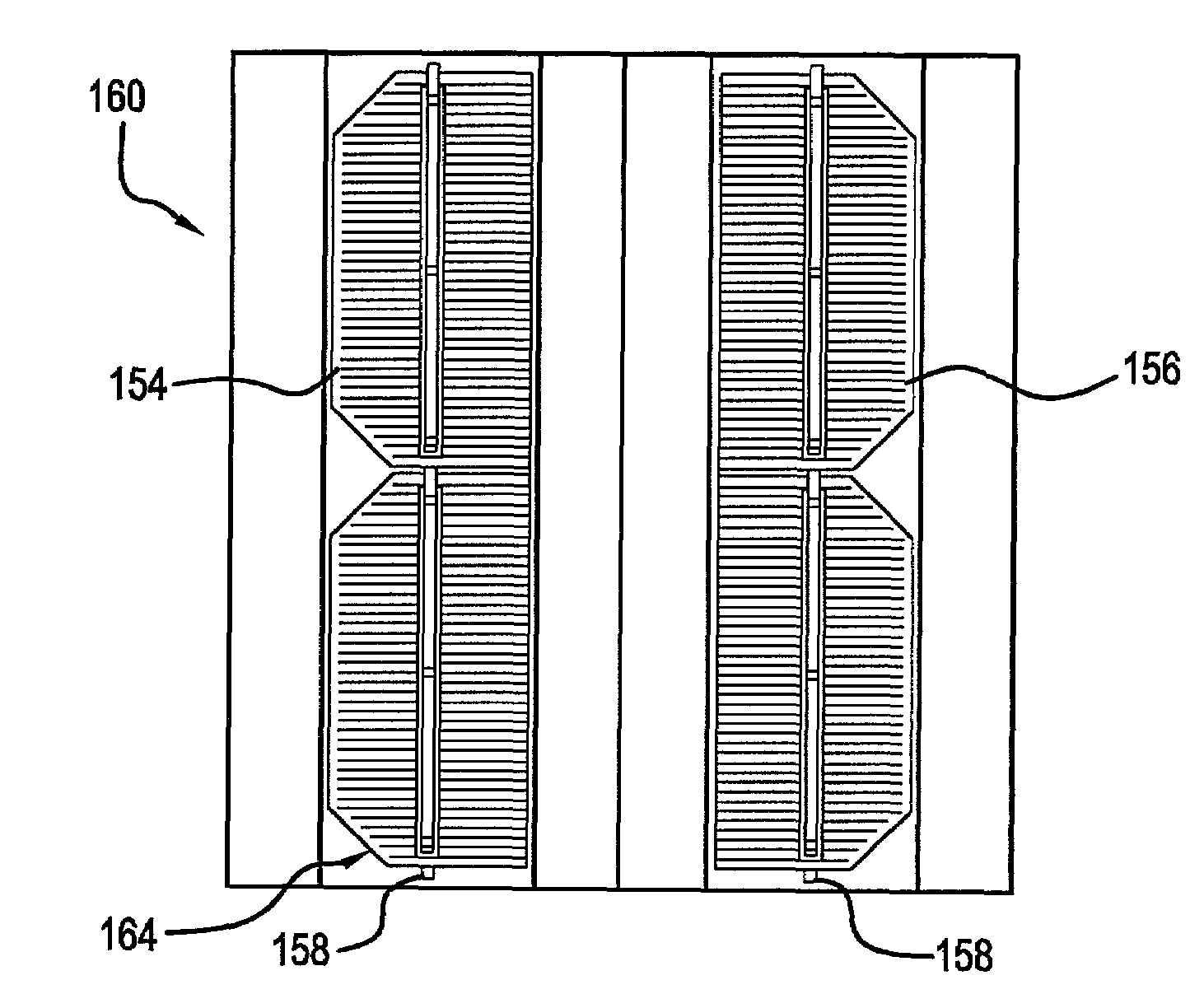
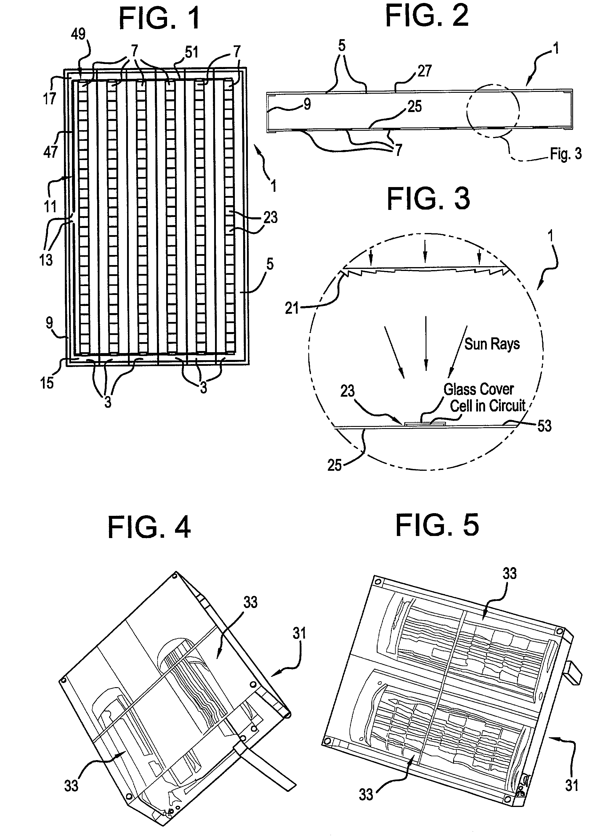
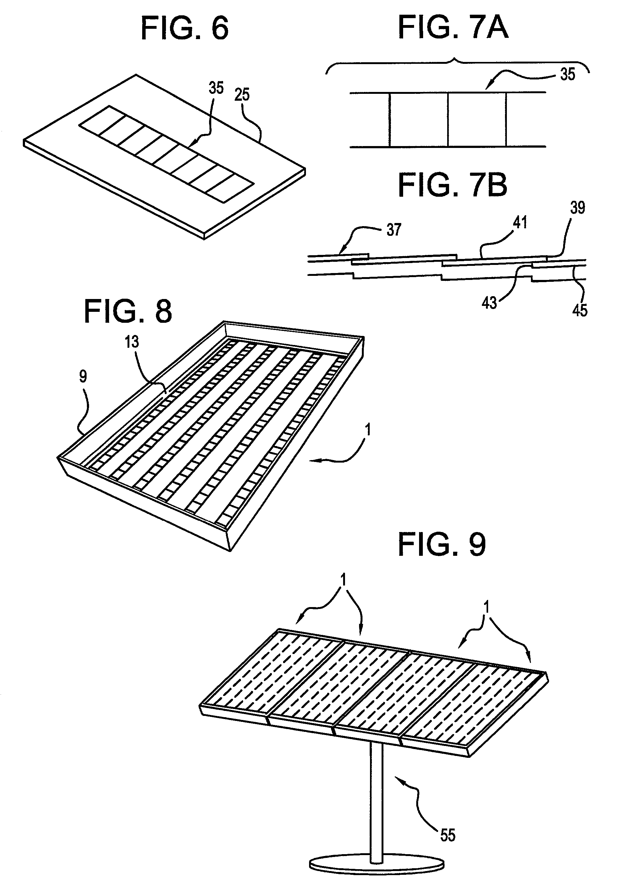
[0052]FIGS. 1, 2, 3, and 8 show a preferred planar concentrator solar power module 1. FIG. 1 shows a top view of the planar solar concentrator power module 1 of the present invention. An array 3 of linear Fresnel lenses 5 produces lines of focused solar radiation that fall on an aligned array of linear photovoltaic power circuits. FIG. 2 shows a cross section through the planar solar concentrator power module 1 of FIG. 1. The cross section is perpendicular to the focal lines produced by the lenses and perpendicular to the circuit length dimension. FIG. 3 shows a blow up section from FIG. 2 showing a single lens 21 and circuit element 23 in more detail.

[0053]The preferred unit depicted is exemplary with dimensions not limited to the following. For example, the preferred unit may measure 25″ by 40″ by 3.25″ deep. The size depicted is exemplary and is similar to 75 W planar modules manufactured by Siemens, Kyocera, and Solarex. All of these modules measure approximately 25″ by 40″ and ...


PUM


Abstract

A planar concentrator solar power module has a planar base, an aligned array of linear photovoltaic cell circuits on the base and an array of linear Fresnel lenses or linear mirrors for directing focused solar radiation on the aligned array of linear photovoltaic cell circuits. The cell circuits are mounted on a back panel which may be a metal back plate. The cell circuit area is less than a total area of the module. Each linear lens or linear mirror has a length greater than a length of the adjacent cell circuit. The cell circuit may have cells mounted in shingle fashion to form a shingled-cell circuit. In an alternative module, linear extrusions on the circuit element have faces for mounting the linear mirrors for deflecting sun rays impinging on each mirror onto the shingled-cells. The linear extrusions are side-wall and inner extrusions with triangular cross-sections. The circuit backplate is encapsulated by lamination for weather protection. The planar module is generally rectangular with alternating rows of linear cell circuits and linear lenses or linear mirrors.

Description

[0001]This application claims the benefit of U.S. Provisional Application No. 60 / 374,808 filed Apr. 24, 2002 and U.S. Provisional Application No. 60 / 391,122 filed Jun. 24, 2002.BACKGROUND OF THE INVENTION[0002]Solar cells generate electricity but at a cost which is too high to compete with electricity from the electric power company. It is generally acknowledged that the solar panel cost will have to drop to approximately $1 to $2 per installed Watt before solar cells can compete in this large potential market. Today's cost for solar panels is in the $6 to $7 per Watt range. Three different approaches have been pursued in attempts to resolve this cost problem.[0003]The conventional approach is to use large silicon solar cells tiled in planar modules where the cell area represents over 80% of the total panel area. The cells in this approach can be single crystal or large grain polycrystalline cells. This approach represents over 90% of the market but the cost of this approach has bot...

Claims


Application Information

Patent Timeline
Patent Type & Authority Patents(United States)
IPC IPC(8): H01L31/0232F24S23/30H01L31/042H01L31/048H01L31/05H01L31/052H01L31/18
CPCH01L31/042H01L31/0504H01L31/02F24J2/085Y02E10/52Y02E10/50F24S23/31
Inventor FRAAS, LEWIS M.FRAAS, JANY X.HUANG, HAN XIANGAVERY, JAMES E.
Owner JX CRYSTALS
Why Eureka
Try Eureka