
Hydraulic multi-coupling with independent single handle rotational disconnect

a multi-coupling, independent technology, applied in the direction of agricultural machinery, construction, agricultural tools and machines, etc., can solve the problems of inability to use a rotational cam for independent coupling release with lever operated design, and difficulty in accessing the see-saw lever movemen

Active Publication Date: 2020-12-24
PARKER INTANGIBLES LLC
View PDF0 Cites 0 Cited by
  • Summary
  • Abstract
  • Description
  • Claims
  • Application Information

AI Technical Summary

Benefits of technology

The present disclosure discusses an improved multi-coupling assembly for a multi-line connection with multiple individual quick couplings. The assembly allows for independent disconnection of a male coupler when female couplers are used in a plural mounted housing assembly. The assembly includes a lever operated multi-coupling that connects with both female and male pressure, and independently disconnects the male coupler using a single rotational lever. The design achieves the advantages of the Marquis see-saw design in a more compact configuration. The assembly also has the ability to release residual pressure in the female coupling cartridges and prevents excessive movement of the female coupling cartridge in the housing. The technical effects of the present disclosure include improved efficiency, compact size, and enhanced functionality of the multi-coupling assembly for multi-line connections.

Problems solved by technology

For instance, when a multi-coupling assembly is installed in a near horizontal (or vertical) orientation, the access to the see-saw lever movement becomes difficult and the advantages of a rotational lever become realized.
Previous designs did not realize the ability to use a rotational cam for independent coupling release with a lever operated design.
Previous couplings were either dependent coupling release mechanisms with the lever perpendicular to the axis of the couplings and parallel to a plane created by the two axes of the couplings, or they were independent using a lever perpendicular to the axis and using a see-saw lever which may be unsuitable for certain vehicle configurations.

Method used


Image

  • Hydraulic multi-coupling with independent single handle rotational disconnect
  • Hydraulic multi-coupling with independent single handle rotational disconnect
  • Hydraulic multi-coupling with independent single handle rotational disconnect

Examples


Embodiment Construction

[0026]Embodiments of the present invention will now be described with reference to the drawings, wherein like reference numerals are used to refer to like elements throughout. It will be understood that the figures are not necessarily to scale.

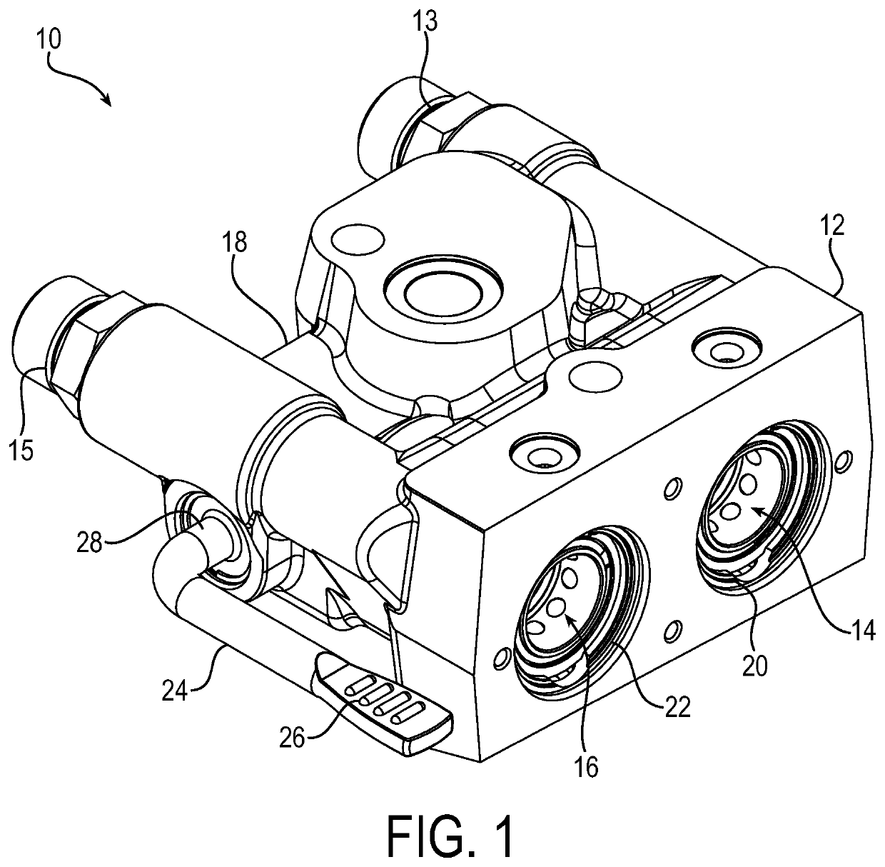
[0027]FIG. 1 is a drawing depicting a perspective view of an exemplary multi-coupling assembly 10 in accordance with embodiments of the present invention. Generally, the multi-coupling assembly 10 includes a plurality of female coupling cartridges that are installed into a block housing or casting 12. As is typical of vehicles usages, the plurality of female coupling cartridges includes two such cartridges, including specifically a first female coupler 14 and a second female coupler 16. The female couplers are connected to respective first and second fluid lines 13 and 15 for the communication of fluid to and from other parts of the hydraulic fluid system. In operation, one of the fluid lines may act as a fluid supply line and the other of the...


PUM


Abstract

A multi-coupling assembly includes a housing, and a first female coupler and a second female coupler that are housed within the housing. Each of the first female coupler and the second female coupler are moveable between a coupling position connectable to a respective male coupler to permit a flow of fluid through the multi-coupling assembly, and a release position in which the male coupler is releasable from a respective female coupler. A rotational lever has a handle portion that is external from the housing and a shaft portion that extends from the handle portion into the housing. Rotation of the rotational lever moves one of the female couplers from the coupling position to the release position without affecting a connection state of the other of the female couplers. Such independent operation of the female couplers is achieved by rotating cams that are configured such that when one of the cams rotates to interact against its respective female coupler, the other of the cams does not act on its respective female coupler. Pressure relief valves are operated such that internal pressure within a female coupler is released prior to the female coupler reaching the release position during a disconnection operation of the male coupler, and prior to the female coupler reaching the coupling position during a connection operation of a male coupler.

Description

RELATED APPLICATIONS[0001]This application claims the benefit of U.S. Provisional Application No. 62 / 672,669 filed May 17, 2018, the contents of which are incorporated herein by reference.FIELD OF INVENTION[0002]The present invention relates generally to quick couplings, and more particularly to multi-couplings for connecting multiple fluid lines in high pressure and other fluid systems, such as hydraulic fluid systems.BACKGROUND OF THE INVENTION[0003]Quick couplings in general are common devices for coupling fluid lines without the need for special tools. Quick couplings, for example, may be configured as individual couplings for the connection of a single fluid line. An exemplary use of quick couplings is in the connection of hydraulic fluid lines in hydraulic systems. Individual quick couplings typically have a ball locking mechanism to hold two halves of the coupling together as they try to separate from internal pressures. Quick couplings may be combined together to be configur...

Claims


Application Information

Patent Timeline
IPC IPC(8): F16L37/00F16L37/56
CPCF16L37/002A01B76/00F16L37/56A01B59/043E02F3/3654E02F9/2275
Inventor FONER, BRIAN K.
Owner PARKER INTANGIBLES LLC
Features
  • Generate Ideas
  • Intellectual Property
  • Life Sciences
  • Materials
  • Tech Scout
  • Unparalleled Data Quality
  • Higher Quality Content
  • 60% Fewer Hallucinations
Learn More