A feeding bowl assembly

a technology of feeding bowl and assembly, which is applied in the field can solve the problems of limited functionality of feeding bowl assembly, accidental or unintentional pushed around the floor of feeding bowl by the animal, and the spillage of food or water contained within the feeding bowl, so as to facilitate the user's locking

Inactive Publication Date: 2021-01-07
PEAK PET PROD LTD
View PDF0 Cites 2 Cited by
  • Summary
  • Abstract
  • Description
  • Claims
  • Application Information

AI Technical Summary

Benefits of technology

[0018]The base may further comprise opening portions for contacting a connector before the connector engages with its complementary connectors. The base may comprise one or more opening portions. The base may comprise any number of opening portions. The base may comprise an even number of opening portions. Each opening portion may comprise an indent in the outside surface of a wall of the base. Each opening portion may be formed on a wall of the base on which a complementary connectors is formed. Each opening portion may comprise a vertical face. Each opening

Problems solved by technology

When an animal eats or drinks from the feeding bowl, the feeding bowl may be pushed around the floor by the animal, either intentionally or unintentionally.
This movement can result in spillage of the food or water contained within the feeding bowl.
However, such a feeding bowl assembly has limited functionality and

Method used


Image

  • A feeding bowl assembly
  • A feeding bowl assembly
  • A feeding bowl assembly

Examples


first embodiment

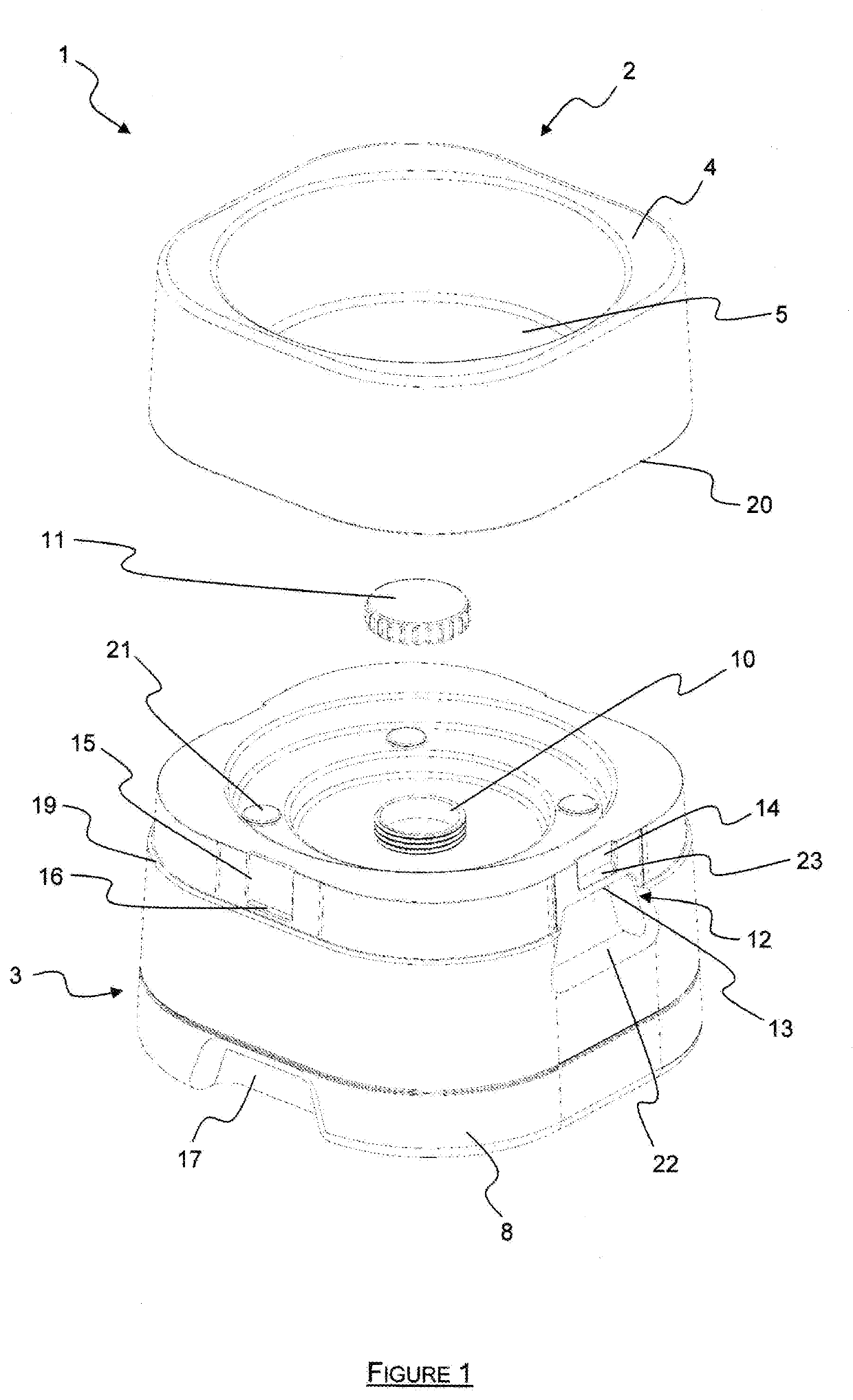
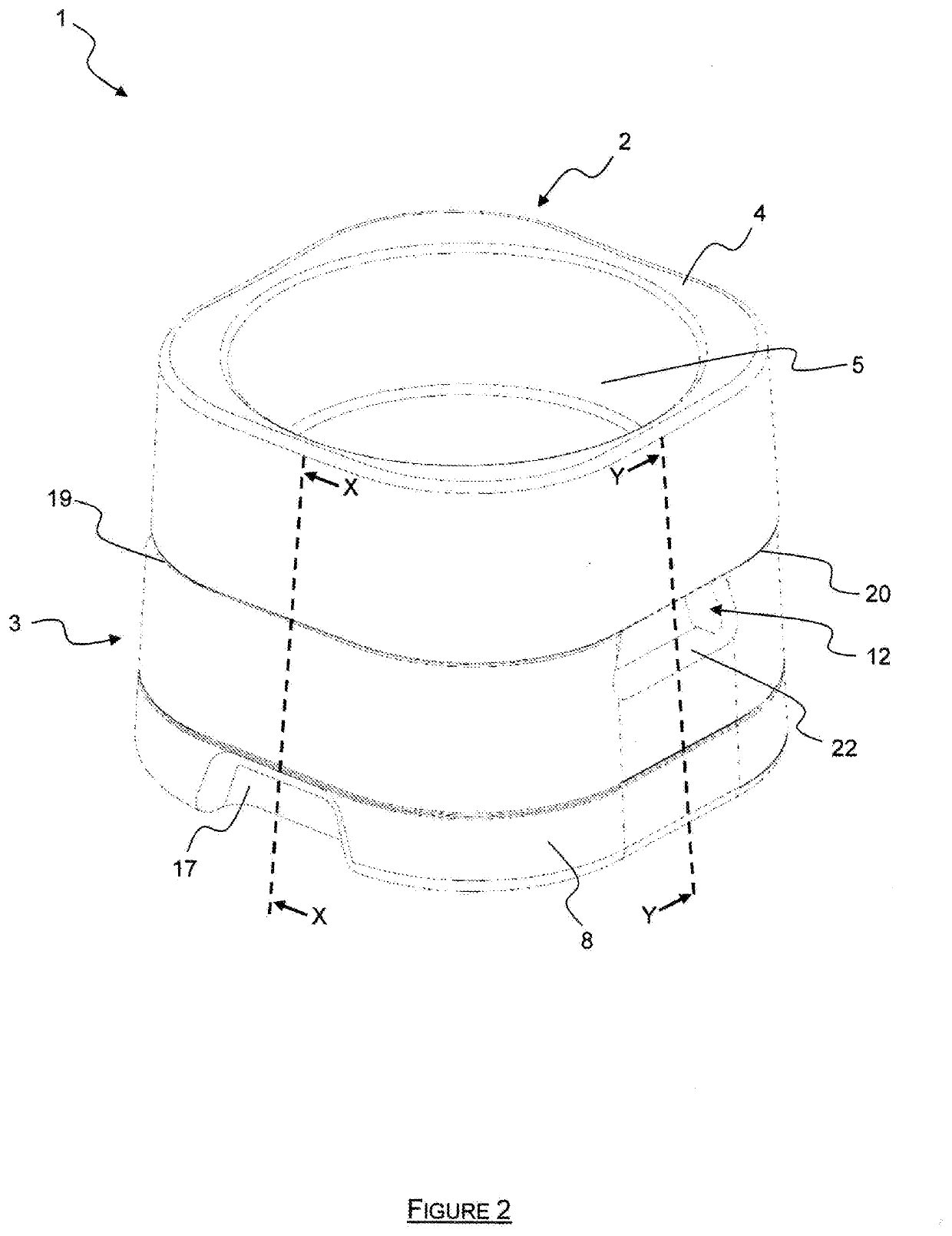
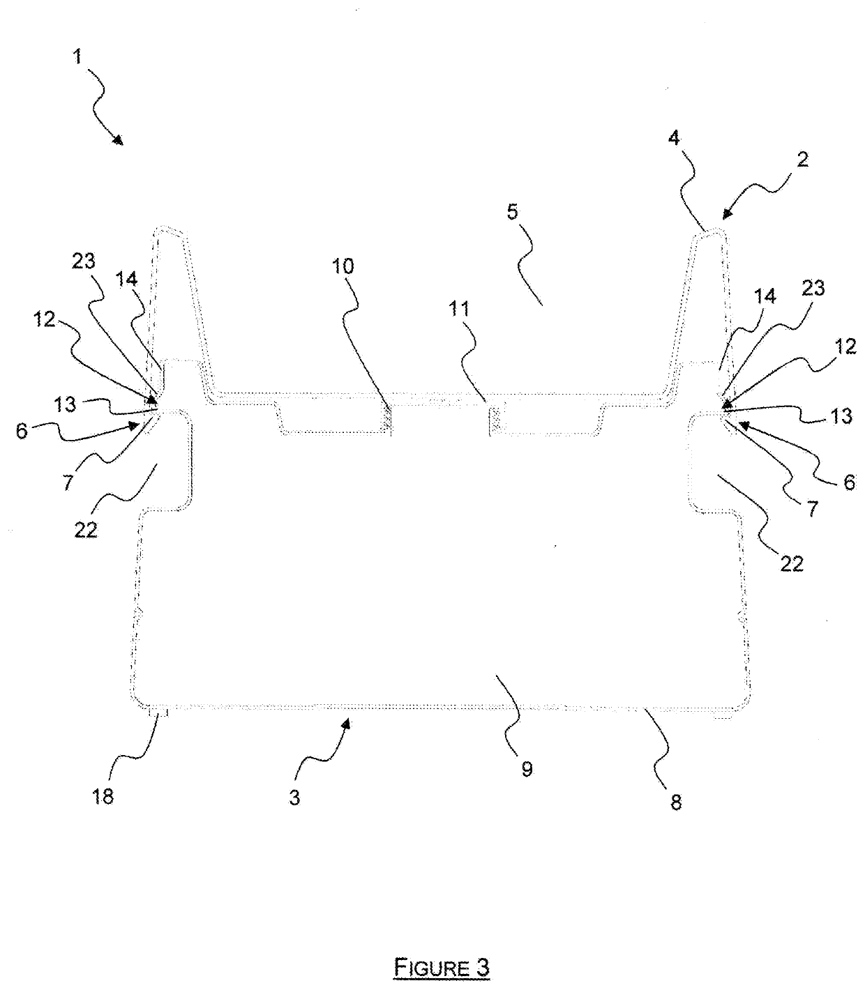
[0059]Referring to FIGS. 1 to 4, a feeding bowl assembly 1 comprises a feeding bowl 2 that is releasably mountable on a base 3. The feeding bowl 2 and base 3 both have substantially the same length and width.

[0060]The feeding bowl 2 comprises a substantially cuboidal body 4 having a substantially square cross section. The body 4 has rounded edges and comprises a cylindrical cavity 5 formed concentrically within the body 4. The body 4 comprises a lower edge 20 at the base of its walls.

[0061]The feeding bowl 2 comprises a pair of connectors 6 formed on opposing inside surfaces of the walls of the body 4. Each connector 6 is a formation having a planar engagement portion 7 that projects inwardly towards the centre of the cavity 5.

[0062]The feeding bowl 2 is formed from a resilient material such as acrylonitrile butadiene styrene such that the connectors 6 may flex.

[0063]The base 3 comprises a substantially cuboidal body 8. The base 3 is hollow, thus defining a cavity, and the cavity of...

second embodiment

In Use

[0107]In a disassembled condition, the bowl 102 and the mounting member 46 are separated from the vessel 32 and wholly outside of the interior 34 and the cavity 120 is open. The ballast material 122 is then located in the cavity 120, ie in the bottom of the interior 34. The ballast material 122 could comprise any suitable weighting material for providing weight, for example, sand, aggregate, stone and / or water. However, it is not recommended to use the cavity 120 for food storage as depletion of the food in the cavity 120 can lead to instability. Also, pets can learn that food is stored in the cavity 120 and then try to access the cavity. By using an inert, stable, smell free ballast material, it is not necessary to provide an air-tight seal to the cavity 120, thus reducing costs.

[0108]The mounting member 46 is then located to sit on the mounting formation 60, so that the closure part 50 substantially closes the cavity 120, preventing escape of the ballast material 122 and con...

third embodiment

[0115]FIG. 6 shows another embodiment of the invention, many features of which are similar to those already described in relation to the embodiment of FIG. 5. Therefore, for the sake of brevity, the following embodiment will only be described in so far as it differs from the embodiment of FIG. 5 already described. Where features are the same or similar, the same reference numerals have been used and the features will not be described again.

[0116]FIG. 6 shows a second animal feeding bowl assembly 201 in which the mounting member 46 is in the form of an inverted bowl which comprises both the spacer part 54 and the closure part 50. The mounting member 46 defines a filling aperture 64. In the assembled condition, the filling aperture 64 comprises part of a filling passage 66, which extends from (and includes) one of the release apertures 42 to the filling aperture 64.

[0117]In use, with the bowl assembly 210 in the assembled condition, the cavity 120 can be filled by inserting a pipe or ...


PUM


Abstract

An animal feeding bowl assembly (101) for domestic pets, the bowl assembly (101) comprising: a bowl (102) for holding animal food (114) and/or drink, a support structure (116) for holding the bowl (102) in use in an assembled condition at an elevated position with reference to a ground or floor surface (118) on which the support structure (116) is located, the support structure (116) defining a cavity (120) below the bowl (102), in which cavity (120) is located, in use, a ballast material (122) for providing stability to the bowl assembly (101), the bowl assembly (101) having a height (28) and a width (30), in which the height (28) is greater than the width (30); the support structure (116) includes a support vessel (32), which defines an interior (34) in which the bowl (102) is located in the assembled condition, and the cavity (120) comprises a lowermost part of the interior (34).

Description

BACKGROUND OF THE INVENTION1. Field of the Invention[0001]The present invention relates to a feeding bowl assembly for feeding small domestic animals, in particular to a feeding bowl assembly comprising a feeding bowl and a base.2. The Prior Art[0002]Animals feeding bowls are often placed on flat, smooth floors. When an animal eats or drinks from the feeding bowl, the feeding bowl may be pushed around the floor by the animal, either intentionally or unintentionally. This movement can result in spillage of the food or water contained within the feeding bowl.[0003]To address this problem, a known feeding bowl assembly comprises a feeding bowl releasably mountable to a weighted base. The feeding bowl can be unlocked from the base to be filled with food or water and then locked to the base to prevent it being moved around on the floor by an animal.[0004]However, such a feeding bowl assembly has limited functionality and it may be difficult for elderly animal owners to unlock and lock th...

Claims


Application Information

Patent Timeline
IPC IPC(8): A01K5/01
CPCA01K5/0135
Inventor PEACOCK, ROBERT PHILIP
Owner PEAK PET PROD LTD
Why Eureka
Try Eureka