Electrophotographic belt and electrophotographic image forming apparatus
- Summary
- Abstract
- Description
- Claims
- Application Information
AI Technical Summary
Benefits of technology
Problems solved by technology
Method used
Image

Examples
example 1
[0091]As shown in Table 3, a surface layer was formed on the outer peripheral surface of the base layer described in the foregoing through the use of a paint, which had been produced in accordance with the surface layer formulation No. 1, as described in the foregoing. In addition, resin particles were produced in accordance with the resin particle formulation No. 1 as described in the foregoing. An electrophotographic belt was produced by causing the resin particles to adhere to the outer surface of the surface layer as described in the foregoing, and was evaluated. The image after the endurance was extremely satisfactory. Production conditions (e.g., the combination of a surface layer formulation and a resin particle formulation) for the electrophotographic belts of the respective examples and comparative examples, and the evaluation results of the belts are shown in Table 3.
Examples 2, 3, 5-1 to 5-4, 6, 7, and 8-1 to 8-4, and Comparative Examples 1 to 3
[0092]Electrophotographic b...
example 4-1
[0095]A coating film of a paint produced in accordance with the surface layer formulation No. 2 was formed on the outer peripheral surface of the base layer described in the foregoing through the use of the paint by the method described in the foregoing. Next, UV light was applied to the coating film until its integrated light quantity became 60 mJ / cm. At this time, the coating film was in such a “semi-cured state” that the coating film did not completely cure, and hence the coating film was in such a state as to easily deform.
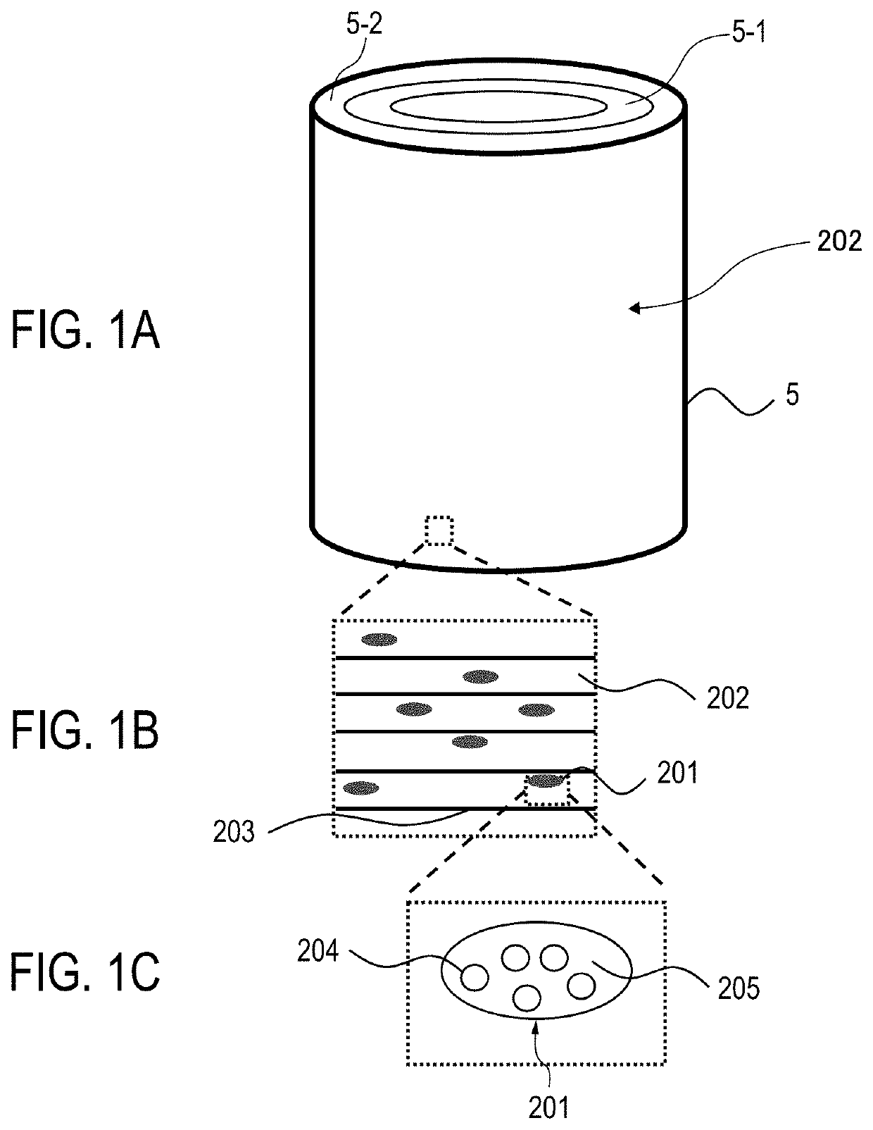
[0096]After that, grooves extending in the peripheral direction of the base layer 5-1 were formed in the outer surface of a coating film 51 in a semi-cured state, which had been formed on the outer peripheral surface of the base layer 5-1, with an imprint processing apparatus illustrated in FIG. 4 by the following method. First, a mold obtained by forming a plurality of convex patterns extending in the peripheral direction on the outer peripheral surface of a ...
example 4-2
[0102]A belt was produced in the same manner as in Example 4-1 except that the cylindrical shape of the cylindrical mold 81 for forming a groove was changed to a reverse crown shape. While the cylindrical shape of the mold 81 was straight in Example 4-1, in this example, the reverse crown shape was adopted so that a pressure concentrated on the end portions of the endless belt. As a result, the amount of the shift was larger in both end portions of the belt than in the central portion thereof. As a result, the resin particles were produced in a larger amount in both the end portions than in the central portion. The convex patterns of the cylindrical mold 81 for forming a groove were the same as those of Example 4-1. A reverse crown amount was as follows: a radius at a center in the axial direction of the cylindrical mold 81 for forming a groove and that at an end therein differed from each other by 5 μm.
[0103]In each of the electrophotographic belts according to Examples 4-1 and 4-2...
PUM
 Abstract
Description
Claims
Application Information
 - R&D Engineer
- R&D Manager
- IP Professional
- Industry Leading Data Capabilities
- Powerful AI technology
- Patent DNA Extraction
Browse by: Latest US Patents, China's latest patents, Technical Efficacy Thesaurus, Application Domain, Technology Topic.
© 2024 PatSnap. All rights reserved.Legal|Privacy policy|Modern Slavery Act Transparency Statement|Sitemap