Electrical connector grounding structure

Active Publication Date: 2021-01-07
ACES ELECTRONICS CO LTD
View PDF0 Cites 1 Cited by
  • Summary
  • Abstract
  • Description
  • Claims
  • Application Information

AI Technical Summary

Benefits of technology

[0007]The present invention has been accomplished under the circumstances in view. It is therefore the main object of the present invention to provide an electrical connector grounding structure, which comprises an electrically insulative terminal holder block, a plurality of conducting terminals, a grounding member, and a shielding shell. The electrically insulative terminal holder block comprises a rectangular base, a mating structure located on the rectangular base, and a fixing structure located on the rectangular base around the mating structure. The conducting terminals are positioned in the rectangular base of the electrically insulative terminal holder block, each having a contact tip located at one end thereof and extended to the mating structure and a connection tip located at an opposite end thereof and extended out of the electrically insulative terminal holder block for bonding to a predetermined circuit board. The grounding member is mounted on the electrically insulative terminal holder block, comprising a first contact structure, a positioning structur

Problems solved by technology

However, with the increase in the transmission speed of electronic signals in various electronic devices today, the high-frequency transmission impedance of each transmission terminal in the board-to-board connector when transmitting electronic signals a

Method used


Image

  • Electrical connector grounding structure
  • Electrical connector grounding structure
  • Electrical connector grounding structure

Examples


Example

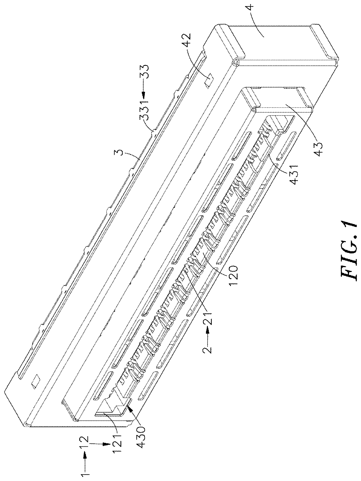
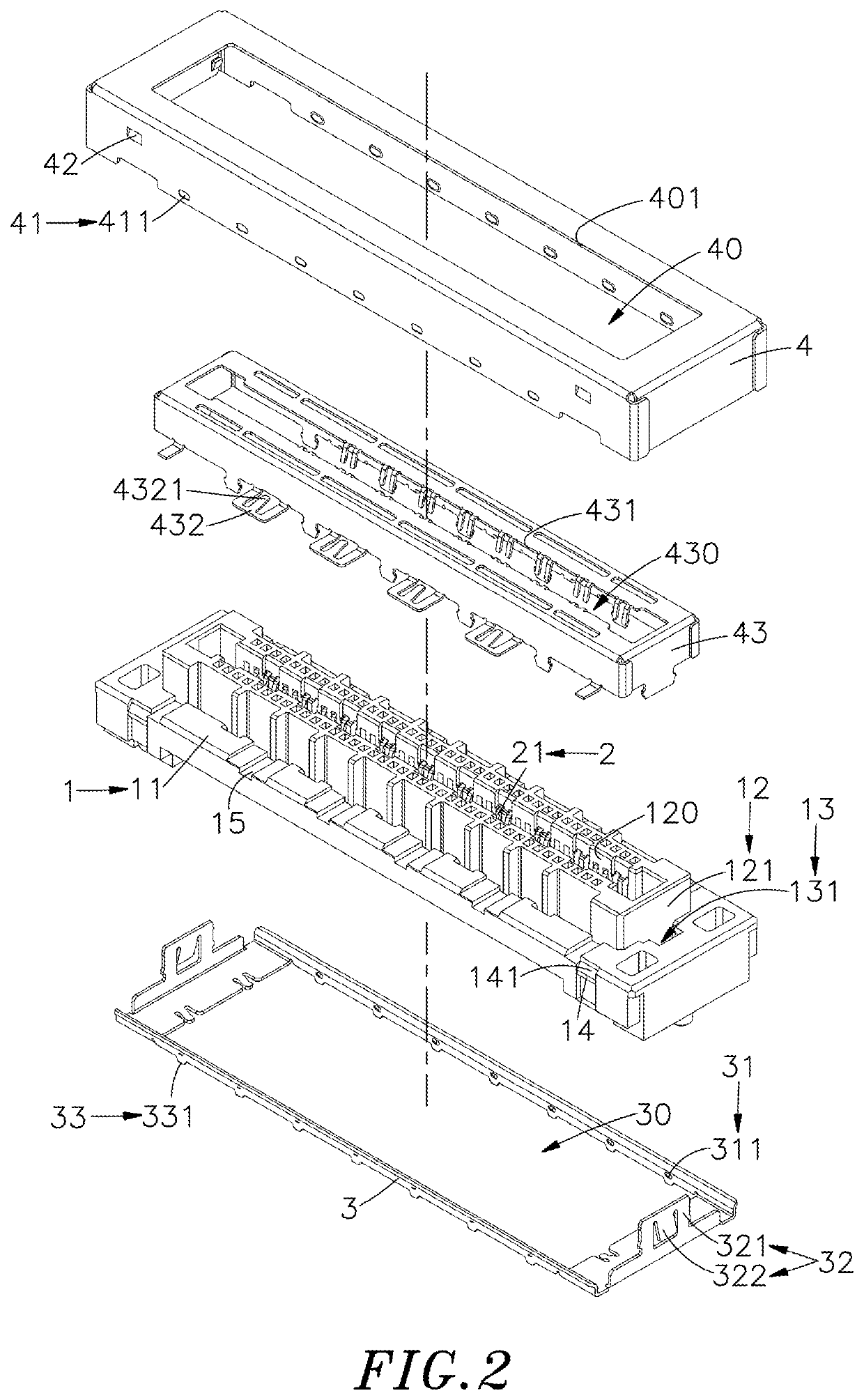
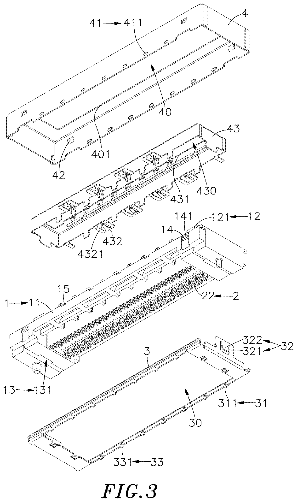
[0021]Referring to FIGS. 1-8, an oblique top elevational view of an electrical connector grounding structure in the form of a female electrical connector in accordance with the present invention, an exploded view of the female electrical connector, another exploded view of the female electrical connector, an oblique top elevational view of the electrical connector grounding structure in the form of a male electrical connector, an exploded view of the male electrical connector, another exploded view of the male electrical connector, a sectional side view of the present invention and another sectional side view of the present invention are shown. As illustrated, the present invention comprises an electrically insulative terminal holder block 1, a plurality of conducting terminals 2, a grounding member 3 and a shielding shell 4.

[0022]The electrically insulative terminal holder block 1 comprises a rectangular base 11, a mating structure 12 provided on a top surface of the rectangular ba...


PUM


Abstract

An electrical connector grounding structure includes an electrically insulative terminal holder block having a rectangular base, a mating structure and a fixing structure, conducting terminals positioned in the rectangular base with contact tips thereof extended to the mating structure and connection tips thereof bonded to a predetermined circuit board, a grounding member having a first contact structure, a positioning structure positioned in the fixing structure and a bonding structure bonded to the circuit board, and a shielding shell covering the electrically insulative terminal holder block and having a second contact structure set in contact with the first contact structure to form a ground loop that guides out electromagnetic waves and crosstalk interference generated during signal transmission.

Description

[0001]This application claims the priority benefit of Taiwan patent application number 108208660, filed on Jul. 3, 2019.BACKGROUND OF THE INVENTION1. Field of the Invention[0002]The present invention relates to electrical connector technology, and more particularly to an electrical connector grounding structure, which uses a grounding member on the electrical connector in contact with a shielding shell to form a ground loop, so that when the multiple conducting terminals of the electrical connector transmit high-frequency signals, the noise can be exported to the circuit board through the grounding member to effectively suppress or filter out electromagnetic wave interference and crosstalk interference, thereby improving the stability of the overall signal transmission.2. Description of the Related Art[0003]Today's technology is developing rapidly, and various electronic devices are constantly evolving. Among them, various electronic components are provided in different electronic d...

Claims


Application Information

Patent Timeline
IPC IPC(8): H01R13/6586H01R12/71H01R13/6596
CPCH01R13/6586H01R13/6596H01R12/716H01R13/6582H01R13/6594H01R24/60H01R2107/00H01R12/52H01R12/7082H01R12/712H01R12/73H01R13/6485H01R13/658H01R13/6581H01R13/6591H01R13/6593H01R13/6595
Inventor CHEN, CHUN-YUAN
Owner ACES ELECTRONICS CO LTD
Why Eureka
Try Eureka