Mining hydraulic constant-resistance deforming and automatic pressure relieving anchor rod and working method thereof

a technology of hydraulic constant resistance and automatic pressure relief, which is applied in the direction of anchoring bolts, mining structures, earthwork drilling and mining, etc., can solve the problems of traditional rigid anchor rod snappage and failure, and achieve the effects of convenient mounting, improved strength of the two structures, and convenient manufactur

Active Publication Date: 2021-01-21
HENAN POLYTECHNIC UNIV
View PDF0 Cites 2 Cited by
  • Summary
  • Abstract
  • Description
  • Claims
  • Application Information

AI Technical Summary

Benefits of technology

[0013](4) when the anchor rod bears tensile stress during supporting, moving the rod body to the right to pull the piston to move to the right, converting the borne tensile stress into compressive stress on the emulsion by the piston, and gradually discharging the emulsion from the pressure relief pipe through the overflow valve during pressure bearing, wherein the deformation of the anchor rod is equal to the length of the sleeve plus the deformation of the rod body; and the complete constant-resistance deformation is realized in the whole hydraulic process, thereby ensuring the bearing capacity of the anchor rod to various stress forms.
[0014]By adopting the above technical solution, the rod body is formed by the threaded connection of the left part and the right part with different outer diameters, which is not only convenient to manufacture, but also convenient to mount; more importantly, the left end of the right part of the rod body is in ejecting contact with the right side of the blocking plate to prevent the piston from moving to the left in the sleeve.
[0015]The piston and the left part of the rod body are integrally formed by casting, which improves the strength of the two structures and avoids damage to the structures due to separation of the piston and the rod body during tension bearing.
[0016]The annular groove is arranged around the rod body at the right side of the piston; and a cross section of the annular groove is a curved surface structure with an opened right end, so that the conversion of tension and compression stress can be realized completely, and a stress concentration phenomenon of compression stress at a joint can also be reduced.
[0017]In conclusion, the constant-resistance deformation of the anchor rod is realized by using the hydraulic technology according to the present invention; and the tensile capacity of the anchor rod and the coping capacity for a series of problems such as high stress and high osmotic pressure faced by deep mining are greatly enhanced, thereby ensuring that the anchor rod still has a strong supporting effect under complex conditions such as high stress and high osmotic pressure in deep mining and truly realizing the constant-resistance pressure relief of the anchor rod.

Problems solved by technology

However, the deformation of the surrounding rock of the roadway tolerable to the traditional rigid anchor rod is generally less than 200 mm, and thus the traditional rigid anchor rod may be snapped and fail due to inadaptability to the large deformation of the surrounding rock of the roadway.

Method used


Image

  • Mining hydraulic constant-resistance deforming and automatic pressure relieving anchor rod and working method thereof
  • Mining hydraulic constant-resistance deforming and automatic pressure relieving anchor rod and working method thereof
  • Mining hydraulic constant-resistance deforming and automatic pressure relieving anchor rod and working method thereof

Examples


Embodiment Construction

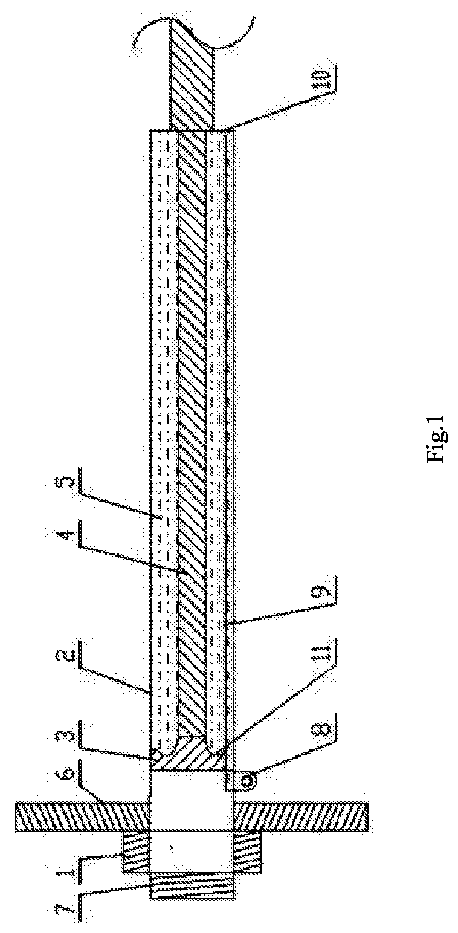
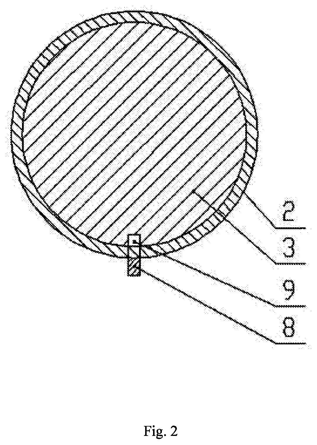
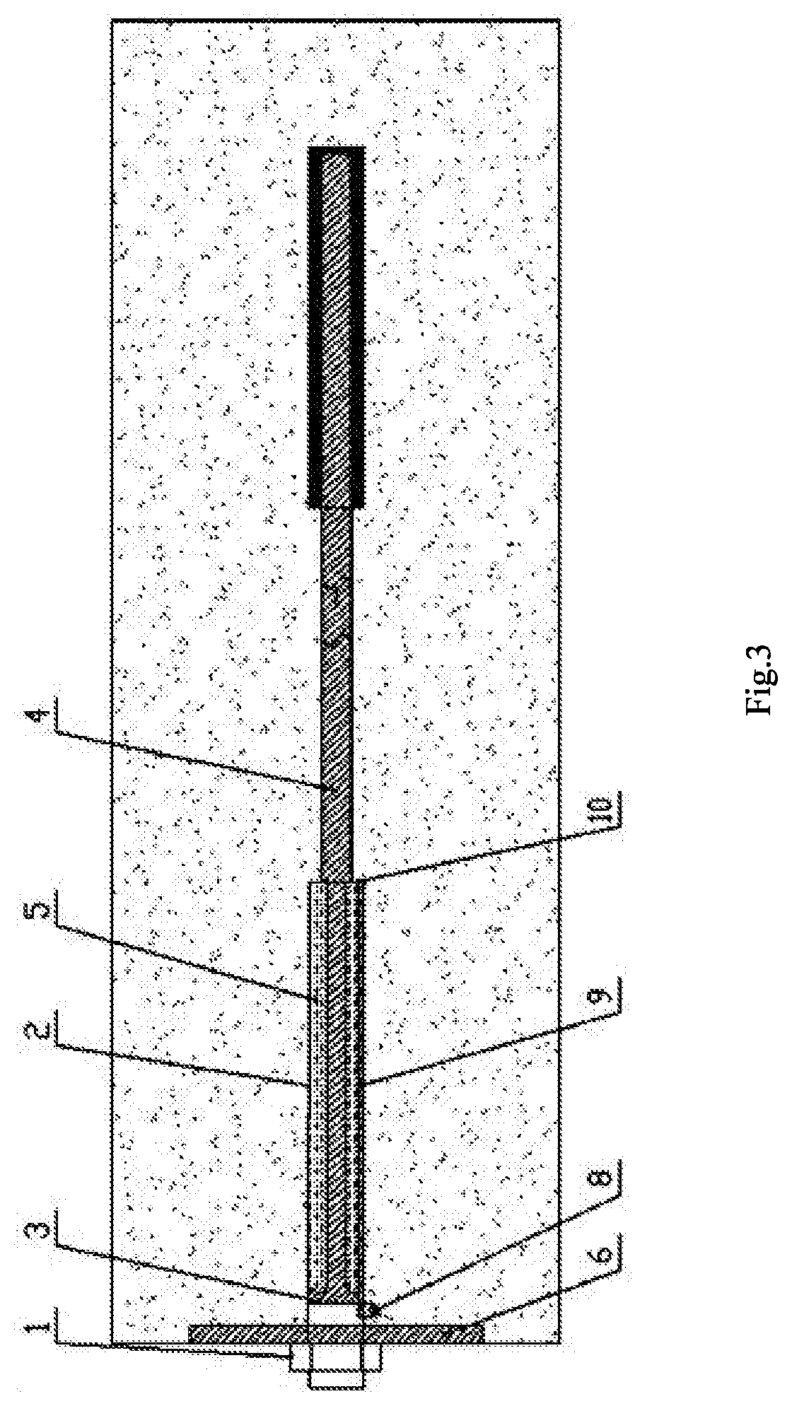
[0022]As shown in FIG. 1 and FIG. 2, a mining hydraulic constant-resistance deforming and automatic pressure relieving anchor rod of the present invention includes a sleeve 2, a pressure relief pipe 9 and a rod body 4 which are arranged in the left-right direction. A left end of the sleeve 2 is open; a blocking plate 10 is arranged at a right end of the sleeve 2; a guide hole is formed in the center of the blocking plate 10; a left part of the rod body 4 penetrates through the guide hole and extends into the sleeve 2; the pressure relief pipe 9 is fixedly arranged on an inner wall of the sleeve 2 in a length direction of the sleeve 2; a gap is formed between a right end of the pressure relief pipe 9 and a left side of the blocking plate 10; an overflow valve 8 is connected to a left end of the pressure relief pipe 9; a piston 3 in sliding sealing fit with the inner wall of the sleeve 2 and an outer wall of the pressure relief pipe 9 is arranged at a left end of the rod body 4; a sea...


PUM


Abstract

An anchor rod includes a sleeve open at one end and having a blocking plate at the other end; a pressure relief pipe fixedly arranged on an inner wall of the sleeve; and a rod body. A guide hole is formed in a center of the blocking plate. A part of the rod body penetrates through the guide hole and extends into the sleeve. A gap is formed between the pressure relief pipe and the blocking plate. An overflow valve is connected to the pressure relief pipe. A piston in sliding seal fit with the sleeve and the pressure relief pipe is arranged at the rod body. A sealing ring in sliding seal fit with the rod body is arranged at the inner wall of the guide hole; and a sealing cavity between the blocking plate and the piston in the sleeve is filled with emulsion.

Description

CROSS-REFERENCE TO RELATED APPLICATIONS[0001]This application is a continuation of International Patent Application No. PCT / CN2019 / 121638, filed on Nov. 28, 2019, which claims the benefit of priority from Chinese Patent Application No. 201910052946.5, filed on Jan. 21, 2019. The content of the aforementioned applications, including any intervening amendments thereto, is incorporated herein by reference.TECHNICAL FIELD[0002]The present invention belongs to the technical field of anchor rod support, and particularly relates to a mining hydraulic constant-resistance deforming and automatic pressure relieving anchor rod and a working method thereof.BACKGROUND OF THE PRESENT INVENTION[0003]Since the first use of anchor rods to support underground roadways in the Siletz Mine in Germany in 1912, the anchor rod support has been widely used in civil engineering (including mining engineering) due to the characteristics of simple structure, convenient construction, low cost and strong adaptabi...

Claims


Application Information

Patent Timeline
Patent Type & Authority Applications(United States)
IPC IPC(8): E21D21/00
CPCE21D21/0046E21D21/008E21D21/0033
Inventor NAN, HUANAN, LONGFEIWEN, YINGMINGFAIZAN, ARSHADHAN, ZHIQIANG
Owner HENAN POLYTECHNIC UNIV
Why Eureka
Try Eureka