
Measurement system and method for automated measurement of several contributions to signal degradation

a measurement system and signal degradation technology, applied in the direction of noise figure or signal-to-noise ratio measurement, instruments, spectral/fourier analysis, etc., can solve the problem that the efficiency of the test device cannot be improved, and achieve the effect of reducing costs, improving accuracy, and reducing errors

Pending Publication Date: 2021-01-21
ROHDE & SCHWARZ GMBH & CO KG
View PDF4 Cites 1 Cited by
  • Summary
  • Abstract
  • Description
  • Claims
  • Application Information

AI Technical Summary

Benefits of technology

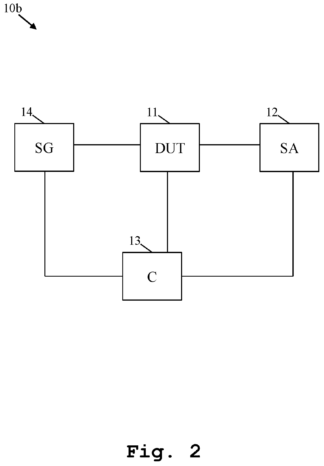
The invention provides a measurement system for automated measurement of signal degradation caused by several factors. The system includes a device under test, a signal analyzer, and a controller. The controller contains command sequences for the device under test and / or the signal analyzer that compensate for specific causes of signal degradation. The system can automatically identify and quantify different causes of signal degradation. The measurement system also includes a signal generator that improves accuracy and efficiency. Overall, the invention ensures high accuracy and efficiency in measuring signal degradation.

Problems solved by technology

Therefore, as a further disadvantage, the respective device under test cannot efficiently be improved on the basis of said common measurement result.

Method used


Image

  • Measurement system and method for automated measurement of several contributions to signal degradation
  • Measurement system and method for automated measurement of several contributions to signal degradation
  • Measurement system and method for automated measurement of several contributions to signal degradation

Examples


Embodiment Construction

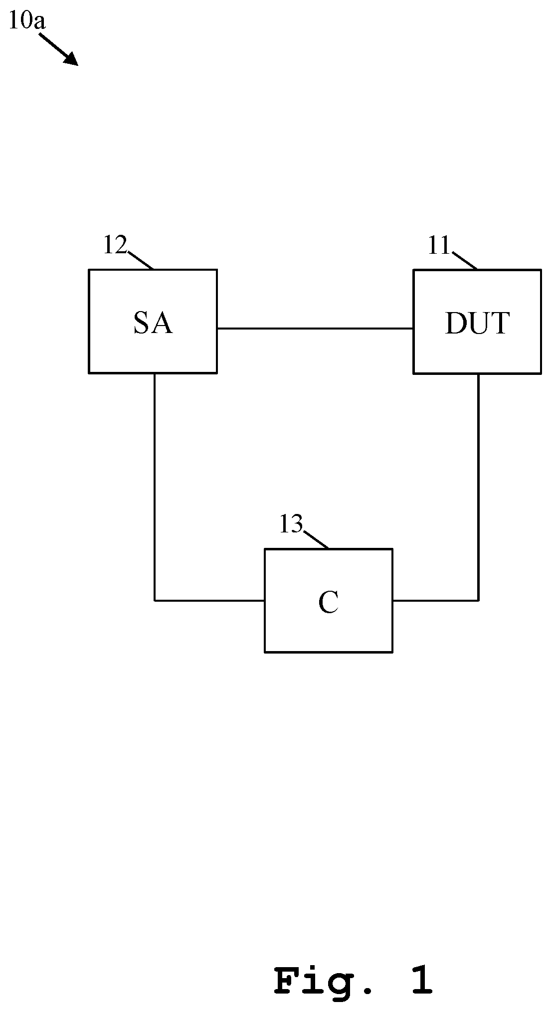
[0034]Firstly, FIG. 1 illustrates a first exemplary embodiment of the inventive measurement system 10a for automated measurement of several contributions to signal degradation. Said measurement system 10a comprises a device under test 11, a signal analyzer 12, and a controller 13. In this context, the controller 13 comprises at least one command sequence for the device under test 11 and / or the signal analyzer 12. In addition to this, each of the at least one command sequence comprises respective commands to compensate for a specific cause of signal degradation.

[0035]As it can further be seen from FIG. 1, the signal analyzer 12 is connected to the device under test 11, whereas the controller 13 is connected to at least one of the device under test 11, the signal analyzer 12, or the combination thereof.

[0036]It is generally noted that the at least one command sequence may also comprise or be at last one test sequence. The at least one command sequence or test sequence, respectively, m...


PUM


Abstract

A measurement system for automated measurement of several contributions to signal degradation is provided. Said measurement system comprises a device under test, a signal analyzer, and a controller. In this context, the controller comprises at least one command sequence for the device under test and / or the signal analyzer. In addition to this, each of the at least one command sequence comprises respective commands to compensate for a specific cause of signal degradation.

Description

TECHNICAL FIELD[0001]The invention relates to a measurement system and a corresponding measurement method for automated measurement of several contributions to signal degradation.BACKGROUND ART[0002]Generally, in times of an increasing number of applications providing communication capabilities, there is a growing need of a measurement system and a corresponding measurement method for performing an automated measurement of several contributions to signal degradation with respect to a device under test comprising such an application in order to verify correct functioning of said applications in a highly accurate and efficient manner.[0003]A method for measuring non-linear distortion using a multi-toned test signal is known from US 2019 / 0064236 A1.[0004]In this context of testing, with the aid of common measuring devices or measurement systems, respectively, only one error vector magnitude (EVM) value can be measured, which describes the respective signal degradation. In addition to t...

Claims


Application Information

Patent Timeline
Patent Type & Authority Applications(United States)
IPC IPC(8): G01R31/317
CPCG01R31/31708G01R31/31711G01R29/26G01R31/00G01R13/0236G01R23/20
Inventor RUENGELER, MATTHIASBUNSEN, BASTIANRAMIAN, FLORIAN
Owner ROHDE & SCHWARZ GMBH & CO KG
Learn More