Valve stent and valve prosthesis

Active Publication Date: 2021-01-28
SHANGHAI MICROPORT CARDIOFLOW MEDTECH CO LTD
View PDF0 Cites 1 Cited by
  • Summary
  • Abstract
  • Description
  • Claims
  • Application Information

AI Technical Summary

Benefits of technology

[0031]In the expanded state, the diameters of the radial sections of the fifth and sixth end portions of the transition tract structure are greater than the diameter of the radial section of the first middle section of the transition tract structure, that is, the transition tract structure is inwardly recessed. On the one hand, the recess is filled with the annulus and leaflets of the natural mitral valve after the valve stent is implanted in the natural mitral valve, which facilitates anchoring the valve stent on the natural mitral valve. On the other hand, the inwardly recessed shape of the transition tract structure facilitates matching with the shape of the annulus of the natural mitral valve, thereby facilitating the positioning of the valve stent and the deploy of the valve stent into the natural mitral valve by the surgeon. In addition, the recess is filled with the annulus and leaflets of the natural mitral valve, so that the valve stent is better covered by the annulus and leaflets of the natural mitral valve, thereby avoiding the blood flowing from the left atrium into the left ventricle through a gap between the natural mitral valve and the valve sten

Problems solved by technology

However, for elderly patients with multi-organ diseases, a history of thoracotomy, and poor cardiac function, conventional surgery has a high risk and a high mortality rate, and some patients don't even have a chance for surgery.
Due to advanced age, complications, and left ventricular dysfunction, up to 50% of symptomatic patients with severe mitral regurgitation are not eligible for conventional mitral valve repair or replacement.
However,

Method used


Image

  • Valve stent and valve prosthesis
  • Valve stent and valve prosthesis
  • Valve stent and valve prosthesis

Examples


embodiment 1

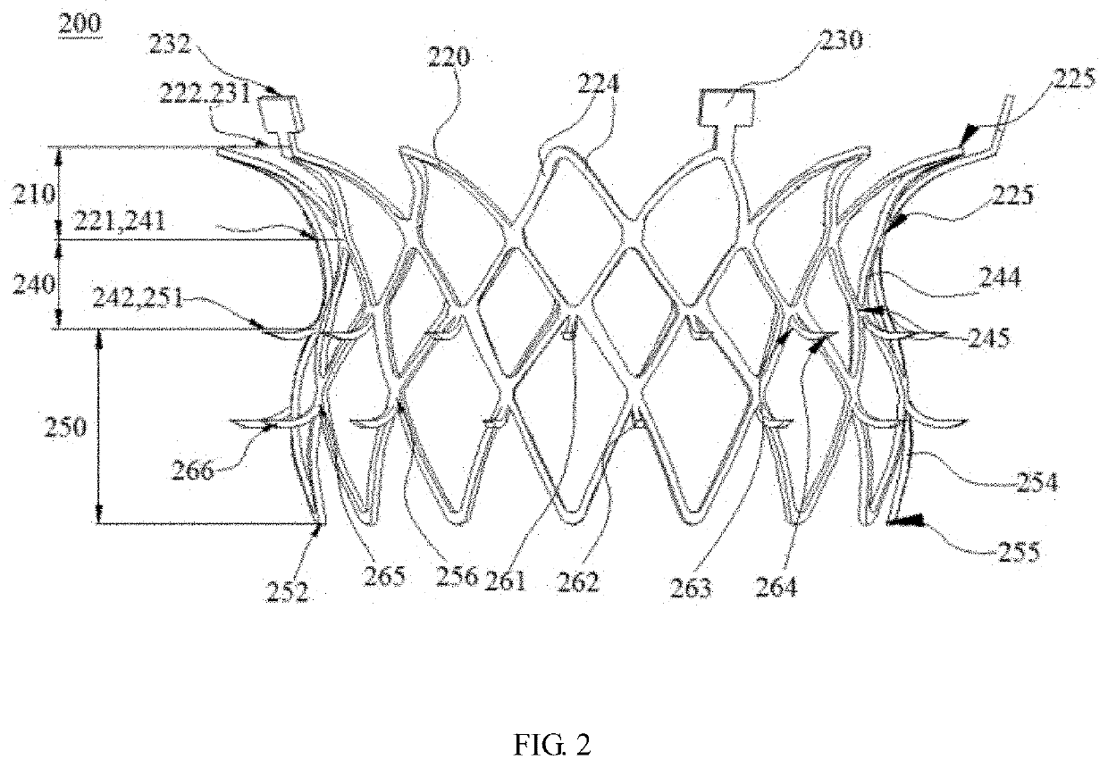
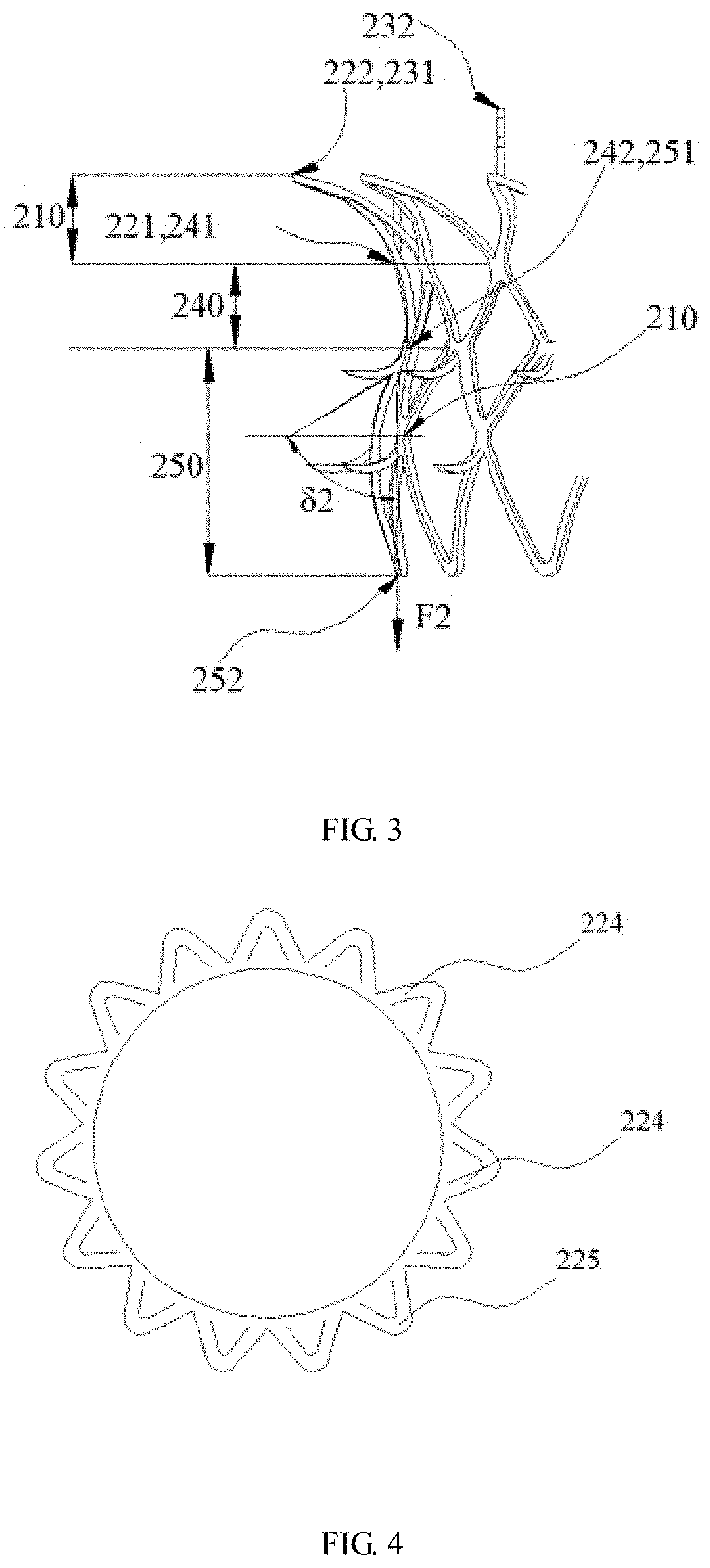
[0072]FIG. 2 is a schematic structural diagram of a valve stent in an expanded state according to Embodiment 1 of the present application. FIG. 3 is a schematic partial enlarged view of a valve stent in an expanded state according to Embodiment 1 of the present application. Referring to FIGS. 2 and 3, this embodiment provides a valve stent 200 which is a self-expanding stent. The valve stent 200 has a compressed state and an expanded state. The valve stent 200 has a central axis (not shown), and the radial sections of the valve stent are perpendicular to the central axis of the valve stent 200. In this embodiment, the central axis is a straight line. In other embodiments, the central axis may also be a curve. The valve stent 200 is in the shape of a mesh tube. Specifically, the radial sections of the valve stent 200 are distributed in a circular ring mode, and the sizes of the radial sections of the valve stent 200 gradually change along the central axis of the valve stent 200. In o...

embodiment 2

[0125]FIG. 13 is a schematic structural diagram of a valve stent in an expanded state according to Embodiment 2 of the present application. FIG. 14 is a schematic perspective view of a valve stent according to Embodiment 2 of the present application. Referring to FIGS. 13 and 14, the difference between the valve stent in this embodiment and the valve stent in Embodiment 1 is that the valve stent 200 in this embodiment further includes an extension structure 270 in the shape of a mesh tube, and the lug 230 is not directly connected to the ring structure 220, but is connected to the ring structure 220 by means of the extension structure 270.

[0126]In this embodiment, the extension structure is fixedly connected to the ring structure. The extension structure 270 has a ninth end portion 271 and a tenth end portion 272. The ninth end portion 271 is fixedly connected to the ring structure 220, and the tenth end portion 272 is away from the ring structure 220 and the transition tract struct...

embodiment 3

[0150]This embodiment provides a valve prosthesis. Referring to FIGS. 22 and 23, FIG. 22 is a front view of a valve prosthesis in an expanded state according to Embodiment 3 of the present application, and FIG. 23 is a top view of a valve prosthesis in an expanded state according to Embodiment 3 of the present application. For example, the valve prosthesis includes the valve stent 200 in the foregoing embodiments and a valve assembly.

[0151]The valve assembly is attached to the valve stent 200. The valve assembly includes a prosthetic leaflet 310 (referring to FIG. 23) and a suture skirt 320 (referring to FIG. 22).

[0152]In this embodiment, the prosthetic leaflet 310 and the suture skirt 320 are attached to the valve stent 200 by means of suture.

[0153]The prosthetic leaflet 310 is sutured inside the transition tract structure 240 and the outflow tract structure 250, and the prosthetic leaflet 310 is used to make blood to flow through the inside of the valve stent 200 from the inflow t...


PUM


Abstract

A valve stent and a valve prosthesis. The valve stent is in the shape of a mesh tube, and has a compressed state and an expanded state. The valve stent includes an inflow tract structure, a transition tract structure, an outflow tract structure, and a barb structure. The transition tract structure has a fifth end portion, a sixth end portion, and a first middle section. In the expanded state, the diameters of the radial sections of the fifth end portion and the sixth end portion are greater than the diameter of the radial section of the first middle section of the transition tract structure. The outflow tract structure has a seventh end portion and an eighth end portion. The seventh end portion of the outflow tract structure is fixedly connected to the sixth end portion of the transition tract structure, and the eighth end portion is a free end. The barb structure is disposed on the transition tract structure and the outflow tract structure, and protrudes towards the outside of the transition tract structure and/or the outflow tract structure. The valve stent and the valve prosthesis can be stably anchored on natural valves.

Description

TECHNICAL FIELD[0001]The present application relates to the technical field of medical instruments and, more specifically, to a valve stent and a valve prosthesis.BACKGROUND[0002]The heart contains four cardiac chambers, wherein the left atrium and left ventricle are on the left side of the heart, and the right atrium and right ventricle are on the right side of the heart. A ventricular inflow tract structure is formed between the atrium and the ventricle, a left ventricular outflow tract structure is formed by the left ventricle and the aorta, and a right ventricular outflow tract structure is formed by the right ventricle and the pulmonary artery. There are valves at the ventricular inflow tract structure, the left ventricular outflow tract structure, and the right ventricular outflow tract structure. The valve has a “one-way valve” function to ensure the normal flow of blood in the cardiac chambers. When a problem occurs in the valve, the heart hemodynamics change, and the heart ...

Claims


Application Information

Patent Timeline
IPC IPC(8): A61F2/24
CPCA61F2/2418A61F2220/0016A61F2/2409A61F2/2412A61F2230/0002A61F2230/0078A61F2230/001
Inventor ZHAO, CHUNXIAYANG, MINGCHEN, GUOMINGLI, YU
Owner SHANGHAI MICROPORT CARDIOFLOW MEDTECH CO LTD
Why Eureka
Try Eureka