Apparatus and method for ascertaining a distance to an object

a distance measurement and distance technology, applied in the field of apparatus and distance measurement method, can solve the problems of inaccurate image reconstruction, increased complexity of structure, increased cost, etc., and achieve the effect of facilitating distance measuremen

Active Publication Date: 2021-01-28
CARL ZEISS SMT GMBH
View PDF9 Cites 4 Cited by
  • Summary
  • Abstract
  • Description
  • Claims
  • Application Information

AI Technical Summary

Benefits of technology

[0014]Against the aforementioned background, it is an object of the present invention to provide an apparatus and a method for ascertaining a distance to an object, which facilitates distance measurement that is as accurate and reliable as possible and which at least partly avoids the above-described disadvantages.

Problems solved by technology

A problem occurring here in practice is that the dispersive scanning device is subjected to changes in its frequency-dependent beam deflection, inter alia on account of thermal variations, with the consequence that the image reconstruction performed is incorrect—on account of a no longer correct assignment between the frequency of the respective measurement beam and the object location impinged by said measurement beam.
Possible approaches for overcoming the above-described problem include measures for thermal stabilization of the dispersive scanning device; however, this increases the complexity of the structure and increases the costs.
A further problem occurring in practice relates to ensuring an unchanging and disturbance-free frequency curve in the optical signal emitted by the light source unit, with the closed-loop control of the frequency or the change in frequency of the emitted optical signal, typically implemented using the aforementioned phase locked loop including the OPLL electronics, representing a formidable challenge.
A further factor increasing the complexity of the structure in respect of the light source unit and the closed-loop control thereof is that, under safety aspects, there needs to be monitoring—preferably redundant monitoring—of the luminous power emitted by the light source unit in order to avoid injury to persons situated in the surroundings.

Method used


Image

  • Apparatus and method for ascertaining a distance to an object
  • Apparatus and method for ascertaining a distance to an object
  • Apparatus and method for ascertaining a distance to an object

Examples


Embodiment Construction

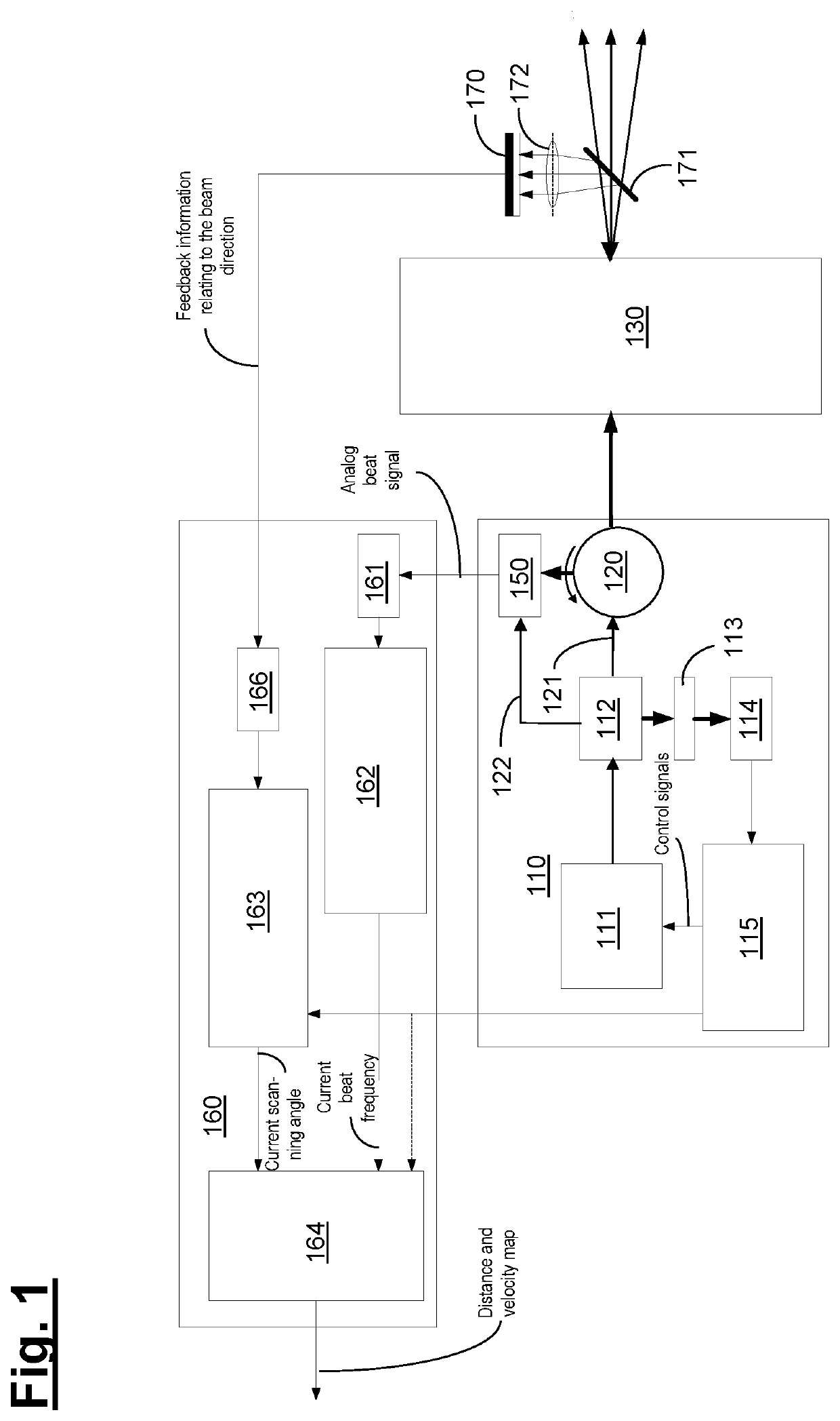
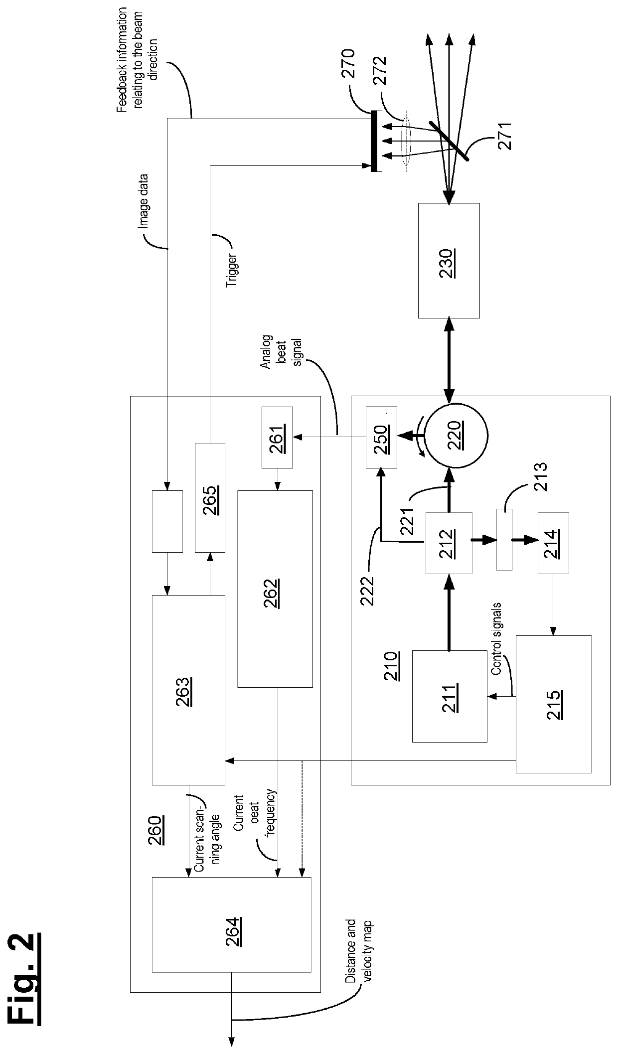
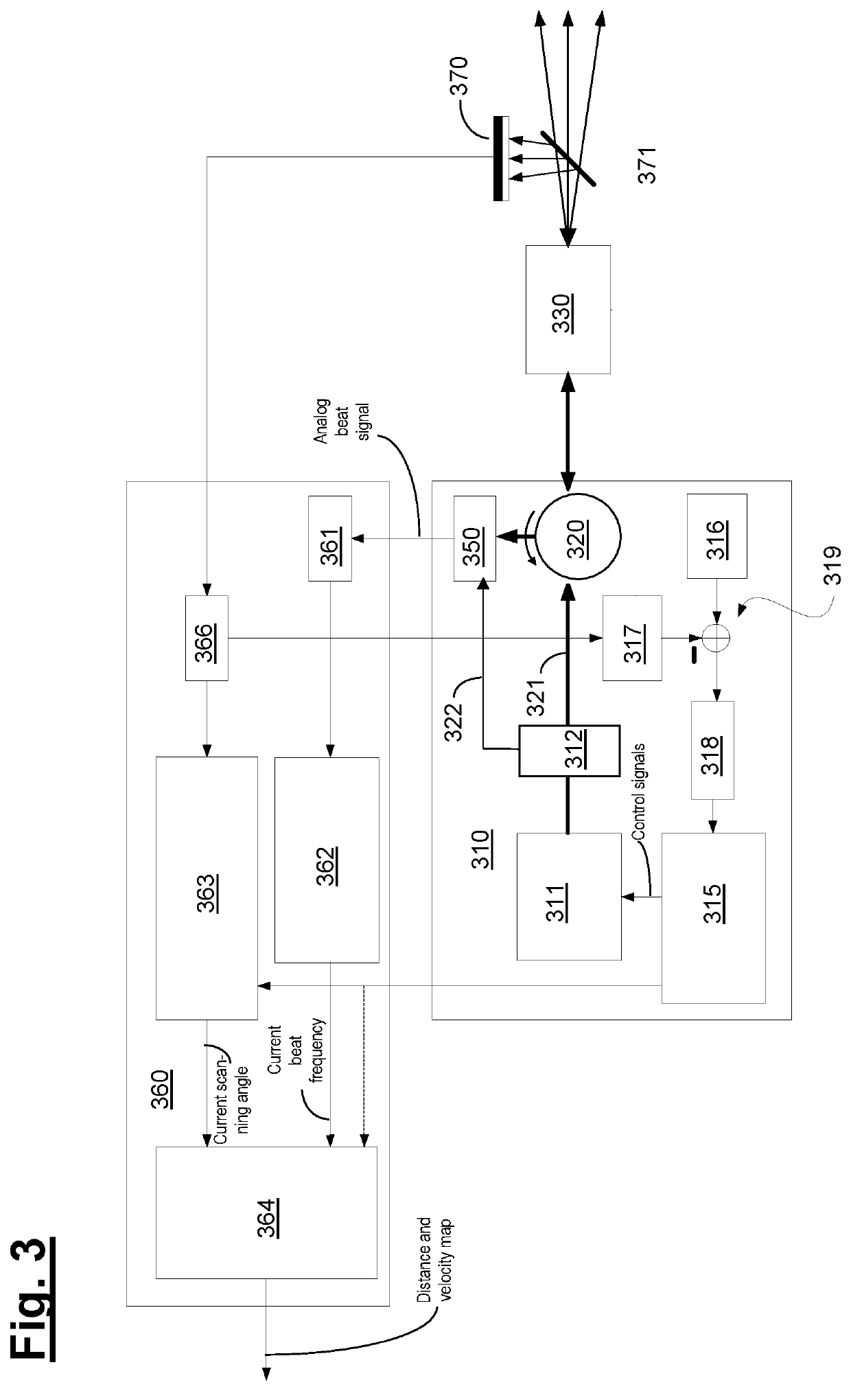
[0049]Below, the structure and functionality of embodiments of an apparatus according to the invention are described with reference to the schematic illustrations of FIGS. 1-5.

[0050]According to FIG. 1, the light source unit 110 comprises a frequency-modulated FMCW laser 111 (FMCW=frequency-modulated continuous wave) for emitting an optical signal with a time-varying frequency (“chirp”). By way of example, the laser 111 could be a DFB laser, a WGMR laser or else a VCSEL laser.

[0051]The light source unit 110 generates optical signals that each have a time-varying frequency according to a specified (in particular linear) frequency curve. To this end, the light source unit 110 comprises—purely in exemplary fashion and without restricting the invention thereto—a beam splitter 112, a Mach-Zehnder interferometer 113 serving as a frequency discriminator and a detector 114, with the possibly amplified output signal of the detector 114 forming the input for a control device 115, which can co...


PUM


Abstract

An apparatus for ascertaining a distance to an object has a light source unit for emitting an optical signal with a time-varying frequency, an evaluation device for ascertaining a distance to the object based on (a) a measurement signal that arose from the signal and was reflected at the object and (b) a reference signal that was not reflected at the object. The apparatus has also a dispersive element disposed in the signal path of the optical signal and an optical position sensor disposed downstream of this dispersive element in the signal path.

Description

CROSS-REFERENCE TO RELATED APPLICATIONS[0001]This application claims benefit of earlier German patent application 102019210999.3 which was filed on Jul. 24, 2019. The entire disclosure of this earlier patent application is incorporated herein by reference.BACKGROUND OF THE INVENTIONField of the Invention[0002]The invention relates to an apparatus and a method for ascertaining a distance to an object. The apparatus and the method can be used to ascertain distances to both moving and stationary objects and, in particular, to ascertain the topography or form of a spatially extended three-dimensional object when used in scanning operations.Description of the Prior Art[0003]For the purposes of measuring the distance to objects by optical means, a measurement principle also referred to as LIDAR is known, amongst others, in which an optical signal is emitted to the relevant object and evaluated after back-reflection has taken place at the object. In practice, use is made both of time-of-fl...

Claims


Application Information

Patent Timeline
Patent Type & Authority Applications(United States)
IPC IPC(8): G01S17/34G01S7/4913
CPCG01S17/34G01S7/4913G01S7/4911G01S7/497G01S17/42
Inventor HORN, JAN
Owner CARL ZEISS SMT GMBH
Why Eureka
Try Eureka