Vacuum suction acne remover with camera function

a technology of acne remover and vacuum suction, applied in the field of intelligent storage technology, can solve the problems of incomplete cleaning, skin pore cleaning device to be used, and still not satisfactory in function, so as to improve the efficiency and cleanliness of acne removal and prevent skin damag

Inactive Publication Date: 2021-02-11
POWER 7 TECH CORP SHENZHEN
View PDF0 Cites 5 Cited by
  • Summary
  • Abstract
  • Description
  • Claims
  • Application Information

AI Technical Summary

Benefits of technology

[0005]The present invention has been accomplished under the circumstances in view. It is therefore the main object of the present invention to provide a vacuum suction acne remover with camera function, which comprises a main control module, a vacuum suction module comprising a suction head and a vacuum pump connected to the suction head and controllable by the main control module to generate a suction force at the suction head for sucking out an acne from the skin, and a camera module having an imaging lens controllable by the main control module to capture the image of the area being sucked by the vacuum suction module. During the suction process of the vacuum suction module, the camera module can be used to observe the image of the suction area, and the suction of the vacuum suction module can be adjusted according to the depth of the acne displayed on the screen to avoid blind acne removing action and incomplete cleaning and to prevent the skin from being damaged due to excessive suction, thereby improving the efficiency and cleanliness of acne removal.

Problems solved by technology

However, it is still not satisfactory in function.
When cleaning the skin pores, it is often difficult for the user to see the cleanliness of the skin pores, so it is possible to stop the cleaning process before the grease dirt is completely removed, resulting in incomplete cleaning.
In addition, it is also possible to continue the cleaning process after the grease dirt has been completely removed, causing the skin pore cleaning device to be used for too long and causing damage to the skin.

Method used


Image

  • Vacuum suction acne remover with camera function
  • Vacuum suction acne remover with camera function
  • Vacuum suction acne remover with camera function

Examples


Embodiment Construction

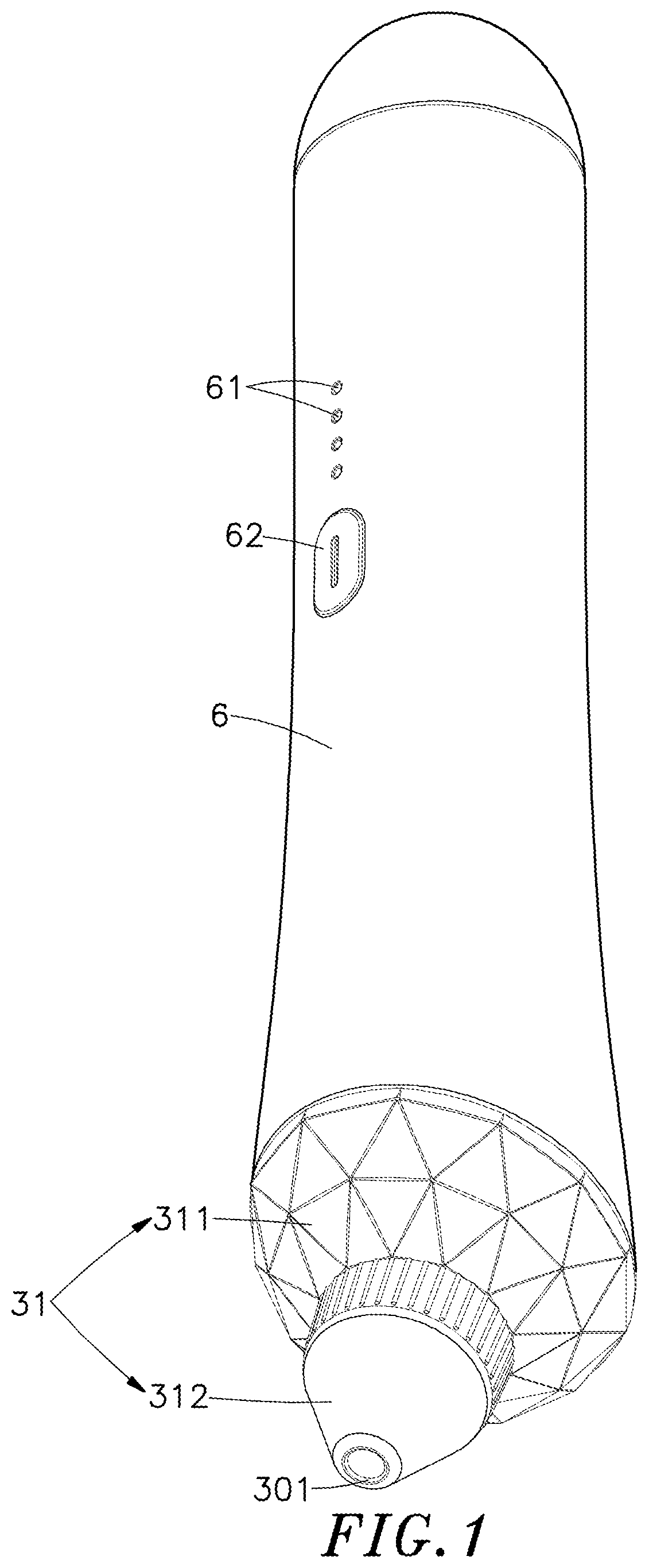
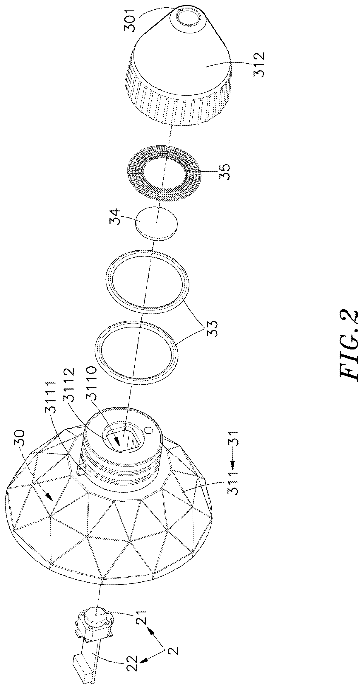
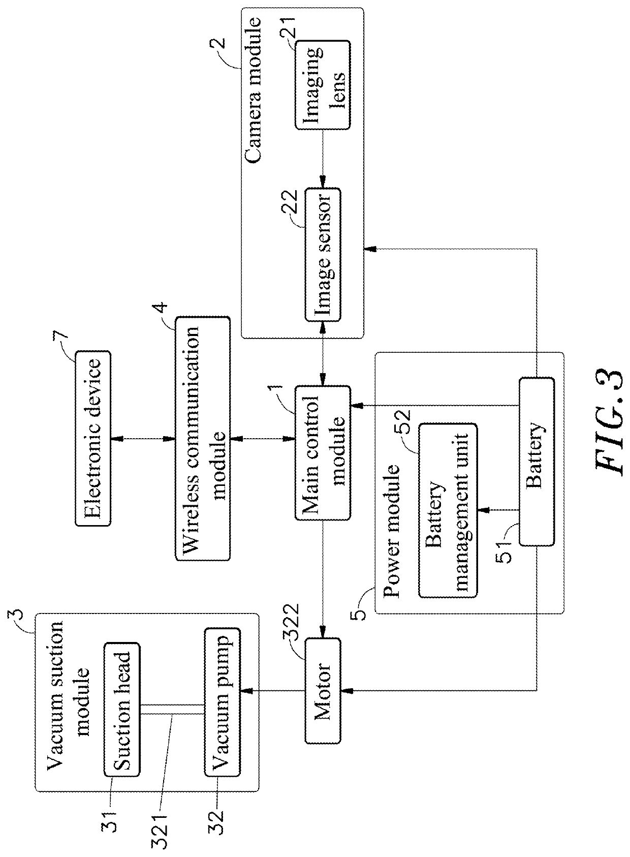
[0013]Referring to FIGS. 1-3, an elevational view of a vacuum suction acne remover with camera function in accordance with the present invention, an exploded view of the camera module and suction head of the vacuum suction acne remover with camera function in accordance with the present invention and a block diagram of the present invention are shown. As illustrated, the vacuum suction acne remover with camera function generally comprises a main control module 1, a camera module 2 and a vacuum suction module 3.

[0014]The main control module 1 is electrically connected with the camera module 2 and the vacuum suction module 3 and configured to control the camera module 2 and the vacuum suction module 3. The main control module 1 can be a multi-media image processing chip, the specific model is an AC1838DG3401 chip, and is connected with the camera module 2 by using an MIPI interface for collecting video data.

[0015]The camera module 2 comprises an imaging lens 21, and an image sensor 22...


PUM


Abstract

A vacuum suction acne remover includes a main control module, a vacuum suction module including a suction head and a vacuum pump connected to the suction head and controllable by the main control module to generate a suction force at the suction head for sucking out acne from the skin, and a camera module having an imaging lens controllable by the main control module to capture the image of the area being sucked by the vacuum suction module. During the suction process of the vacuum suction module, the camera module can observe the image of the suction area, and the suction of the vacuum suction module can be adjusted according to the depth of the acne displayed on the screen to avoid blind acne removing action and incomplete cleaning and to prevent the skin from being damaged due to excessive suction, thereby improving the efficiency and cleanliness of acne removal.

Description

1. FIELD OF THE INVENTION[0001]The present invention relates to intelligent storage technology and more particularly, to a vacuum suction acne remover with camera function, which uses a camera module to capture the image of the skin area being sucked by the vacuum suction module. Thus, during the suction process to remove the acne, the camera module can be used to observe the image of the suction area, and the suction force can be adjusted according to the depth of the acne displayed on the screen to avoid blind acne removing action and incomplete cleaning and to prevent the skin from being damaged due to excessive suction.2. DESCRIPTION OF THE RELATED ART[0002]Generally, blackheads are removed by instrumental suction. The instrumental suction method mainly removes blackheads from the skin through an electric blackhead remover. An electric blackhead remover includes a remover body and a suction head mounted on the top of the remover body. The housing accommodates therein a vacuum pu...

Claims


Application Information

Patent Timeline
Patent Type & Authority Applications(United States)
IPC IPC(8): A61M1/00A61B90/80H04N7/18H04N5/225
CPCA61M1/0066A61B90/80H04N7/183B08B5/04H04N5/2254A61M2205/3584A61M2205/8206H04N5/2253A61M2205/3592A61M2205/583A61M2210/04A61M1/75A61M1/73H04N23/57A61M1/80H04N23/54H04N23/55
Inventor CHEN, MIKEZHANG, YAN-QIU
Owner POWER 7 TECH CORP SHENZHEN
Why Eureka
Try Eureka