
Acoustic emitter device for regular cleaning of a downhole filter

Pending Publication Date: 2021-02-11
KOROSTELEV SERGEY VICTOROVICH
View PDF0 Cites 1 Cited by
  • Summary
  • Abstract
  • Description
  • Claims
  • Application Information

AI Technical Summary

Benefits of technology

The invention is a device for cleaning the inside of filters in wells using ultrasonic waves. The device has a rotating part with a ultrasonic transducer block and a motor that causes the device to move back and forth along the filter's axis. This allows the ultrasonic waves to sweep the entire inside of the filter while also cleaning the pre-filter zone of the well without needing to remove the equipment. The device is designed to increase the area of the working surface, which makes it more effective at treating the filter.

Problems solved by technology

The disadvantage of this method is the need to dismantle the water-lifting equipment every time the well productivity decreases to a critical level.
The disadvantage of such acoustic emitter has to do with the fact that in case of a small inner diameter of the downhole filter, only small-sized ultrasonic vibration systems with limited working surface of the waveguide tool can be used.
Such ultrasonic vibration sources have small projected dimensions of ultrasonic flow onto the filter, which requires a large number of ultrasonic transducer blocks and, hence, significantly complicates the design of the acoustic emitter.

Method used


Image

  • Acoustic emitter device for regular cleaning of a downhole filter
  • Acoustic emitter device for regular cleaning of a downhole filter
  • Acoustic emitter device for regular cleaning of a downhole filter

Examples


Embodiment Construction

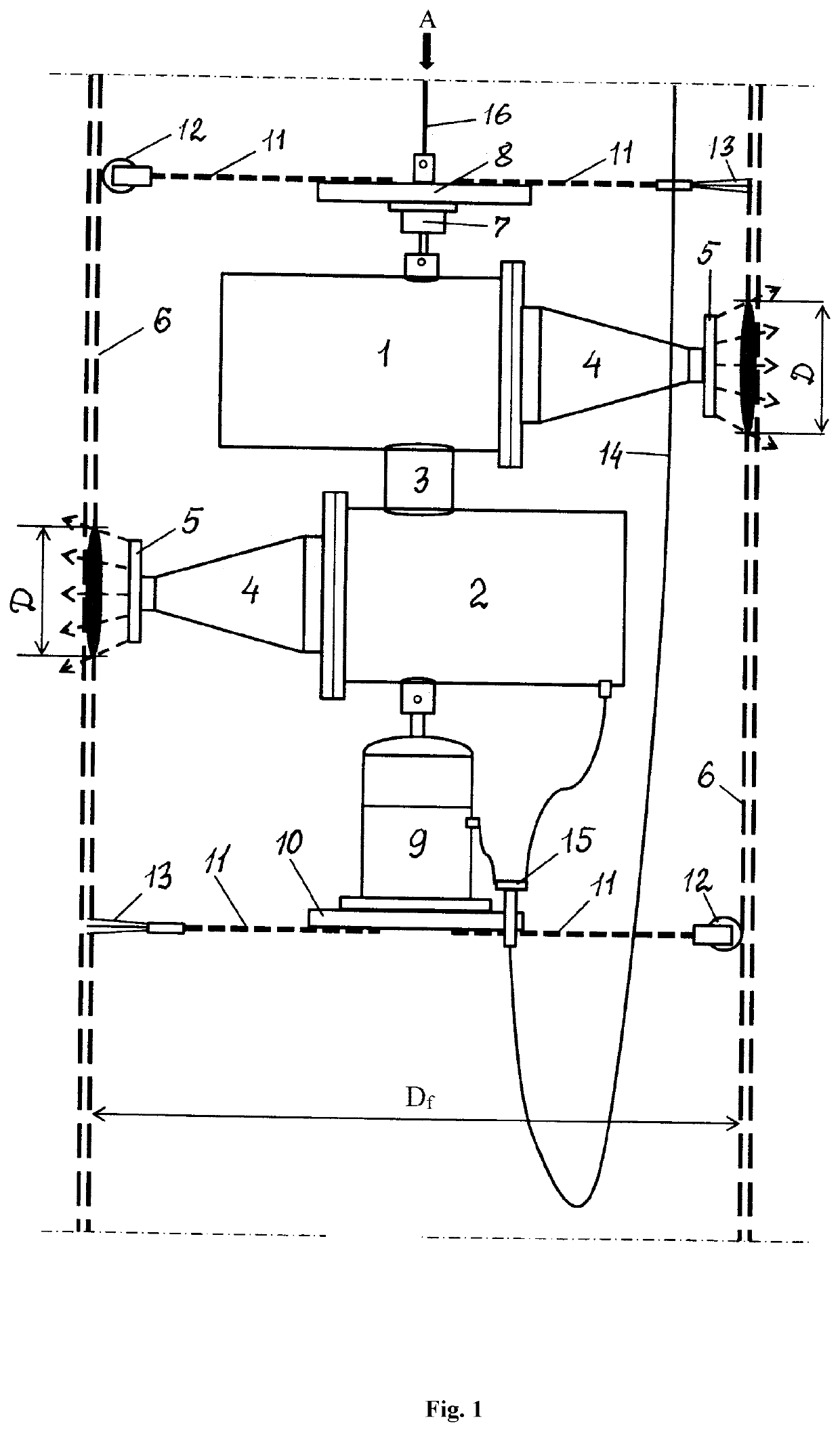
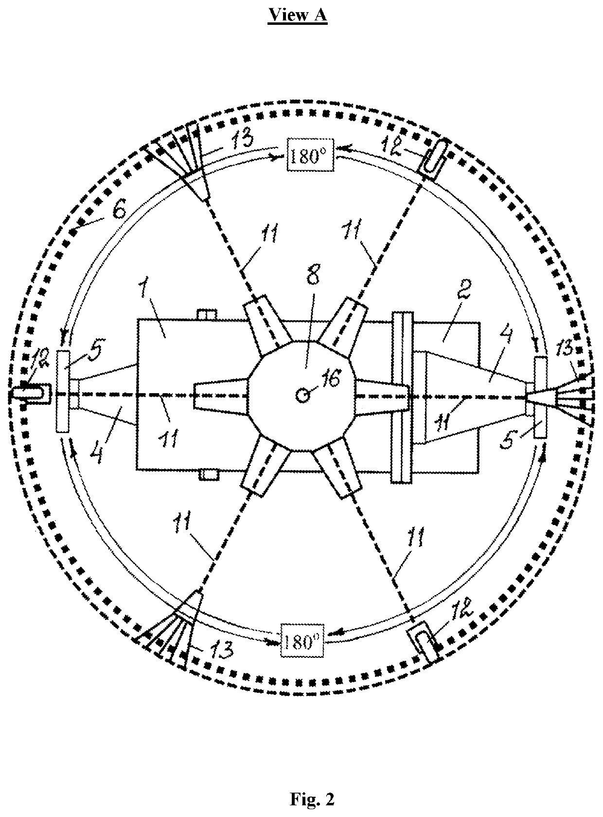
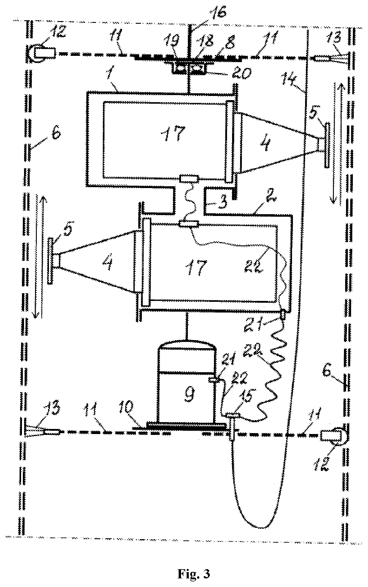
[0018]In the embodiment of the invention, used as an example, high-capacity ultrasonic vibration systems with high amplitude of vibrations require the use of the large-diameter disk-type piezoelectric elements, which results in an increase in the overall dimensions of the vibration system as a whole. In order to be placed within an acoustic emitter, the ultrasonic transducer block (FIG. 1) is made of two cylindrical housings (upper (1) and lower (2)) interconnected by a pipe (3). The axes of symmetry of housings (1) and (2) are parallel and shifted along the filter axis. A single ultrasonic vibration system is installed within each of the housings (1) and (2). The concentrating plates (4) of the systems are oriented in the opposite directions to ensure that the working surfaces of waveguide tools (5) are located directly in front of the inner surface of filter (6). Housing (1) is attached to an upper supporting plate (8) via a rotary unit (7), while housing (2) is attached to a lowe...


PUM


Abstract

The invention relates to methods for restoring well productivity and to devices for cleaning downhole mesh filters without disassembling water-lifting equipment. Well productivity is restored and maintained using an acoustic method based on generating an ultrasonic fluid flow directed at a filter to clean the pre-filter zone of clogging deposits by moving an acoustic emitter along the filter. The acoustic emitter is placed within the lower portion of a casing string, downstream of a submersible downhole pump, and is connected to a means for delivering thereof into the filter zone. The acoustic emitter device comprises an ultrasonic transducer block, which is disposed between two supporting plates and is connected therewith by a rotary unit and an electric motor. The ultrasonic transducer block is configured in the form of two ultrasonic vibration systems located inside separate cylindrical housings positioned transverse to the axis of the filter, while the working surfaces of the waveguide tools of the vibration systems are oriented in the opposite directions toward the inside surface of the filter. The rotary unit and electric motor are connected to the ultrasonic transducer block and are mounted on the upper and lower supporting plates, respectively. The faces of the supporting plates are perpendicular to the filter axis and have bracing elements along the perimeter for anchoring inside the filter. The electric motor is used to facilitate rotary oscillations of the ultrasonic transducers within a 180-degree range (similar to a clock pendulum). In this case, the waveguide tools sweep the inner surface of the filter with an ultrasonic fluid flow along the circumference of the filter within a 360-degree range. Concurrently with this process, the delivery means causes the acoustic emitter to perform reciprocating movement along the filter axis, thus, providing a subsequent treatment of the entire inner surface of the downhole filter with a directed ultrasonic fluid flow, as well as a regular cleaning of the pre-filter zone of the well without disassembling the water-lifting string and submersible pump.

Description

FIELD OF THE INVENTION[0001]The proposed invention relates to the oil and gas industry as well as water utilization system, and specifically, to methods for restoring the well productivity and devices for cleaning a filter under the downhole conditions.BACKGROUND OF THE INVENTION[0002]Since the well productivity (specific yield) decreases over time due to clogging of the mesh filter and surrounding gravel pack with various types of colmatants (contaminants), it becomes necessary to perform an unscheduled well shutdown for a periodic cleaning of the filter and pre-filter zone of the well.[0003]An acoustic method of filter decolmatation is known, which utilizes magnetostrictive or piezoelectric ultrasonic emitters (V. S. Alekseev and V. G. Grebennikov, Restoring an Output of Water-supply Wells [in Russian], Agropromizdat, Moscow (1987), p. 156). The method provides a wide range of emitted oscillation frequencies and the ability to generate a high-energy liquid cavitation flow, which a...

Claims


Application Information

Patent Timeline
IPC IPC(8): B08B9/043E21B37/08
CPCB08B9/0433B08B2203/0288E21B37/08E03B3/18B08B9/027
Inventor KOROSTELEV, SERGEY VICTOROVICH
Owner KOROSTELEV SERGEY VICTOROVICH
Features
  • Generate Ideas
  • Intellectual Property
  • Life Sciences
  • Materials
  • Tech Scout
  • Unparalleled Data Quality
  • Higher Quality Content
  • 60% Fewer Hallucinations
Learn More