
External tensioning Anti-skid chain for an automobile

a technology of anti-skid chain and external tension, which is applied in the direction of non-skid devices, vehicle components, transportation and packaging, etc., can solve the problems of reduced transportation efficiency, reduced vehicle safety, and reduced vehicle safety, so as to improve the enthusiasm of drivers, reduce traffic accidents, and facilitate the effect of promotion

Pending Publication Date: 2021-02-11
ZHUANG LE
View PDF8 Cites 0 Cited by
  • Summary
  • Abstract
  • Description
  • Claims
  • Application Information

AI Technical Summary

Benefits of technology

The present invention has the advantage of being easy to install, even for people with little mechanical knowledge. It can be installed without any need for inside operation, making it even safer in the dark or in poor lighting conditions. Additionally, the invention is cost-effective and can be widely distributed to the society. The invention is convenient to use and helps drivers actively install and use it, reducing traffic accidents and preventing property and life loss. Overall, the invention is a toolless and outsider installation that simplifies disassembly and installation.

Problems solved by technology

Serious problems will occur in the effective output of engine power, the maneuverability of automobile direction, and the effectiveness of braking.
This will not only reduce transport efficiency, resulting in traffic paralysis, and often lead to the tragic loss of life.
There are many kinds of anti-skid chains, but they generally have one common weakness: inconvenience.
Even for young and strong professional drivers, installing and removing anti-skid chains is not a simple or easy task.
For the large number of family car users, especially the elderly and young ladies among them, it is even more difficult to cope with.
The serious inconvenience of installation and disassembly of automobile anti-skid chain objectively leads to a rather negative reality.
Many people do not buy skid chains at all.
Some people have purchased the anti-skid chain, but do not install and use it timely.
Some people want to install the chain when the road is frozen, but they are unable to do it.
Some manufacturers, aiming to reduce the difficulty of installation, deliberately increase adjacent anti-skid chain distribution distance, so that the tire often directly contact with the ice in the absence of the participation of anti-skid strip.
In this case, it is extremely easy to lose control when in need of accurate control of the direction and effective braking.
That is to say, the inconvenience of installation and disassembly of automobile anti-skid chain greatly restricts the normal function of anti-skid chain.

Method used


Image

  • External tensioning Anti-skid chain for an automobile
  • External tensioning Anti-skid chain for an automobile
  • External tensioning Anti-skid chain for an automobile

Examples


implementation example 1

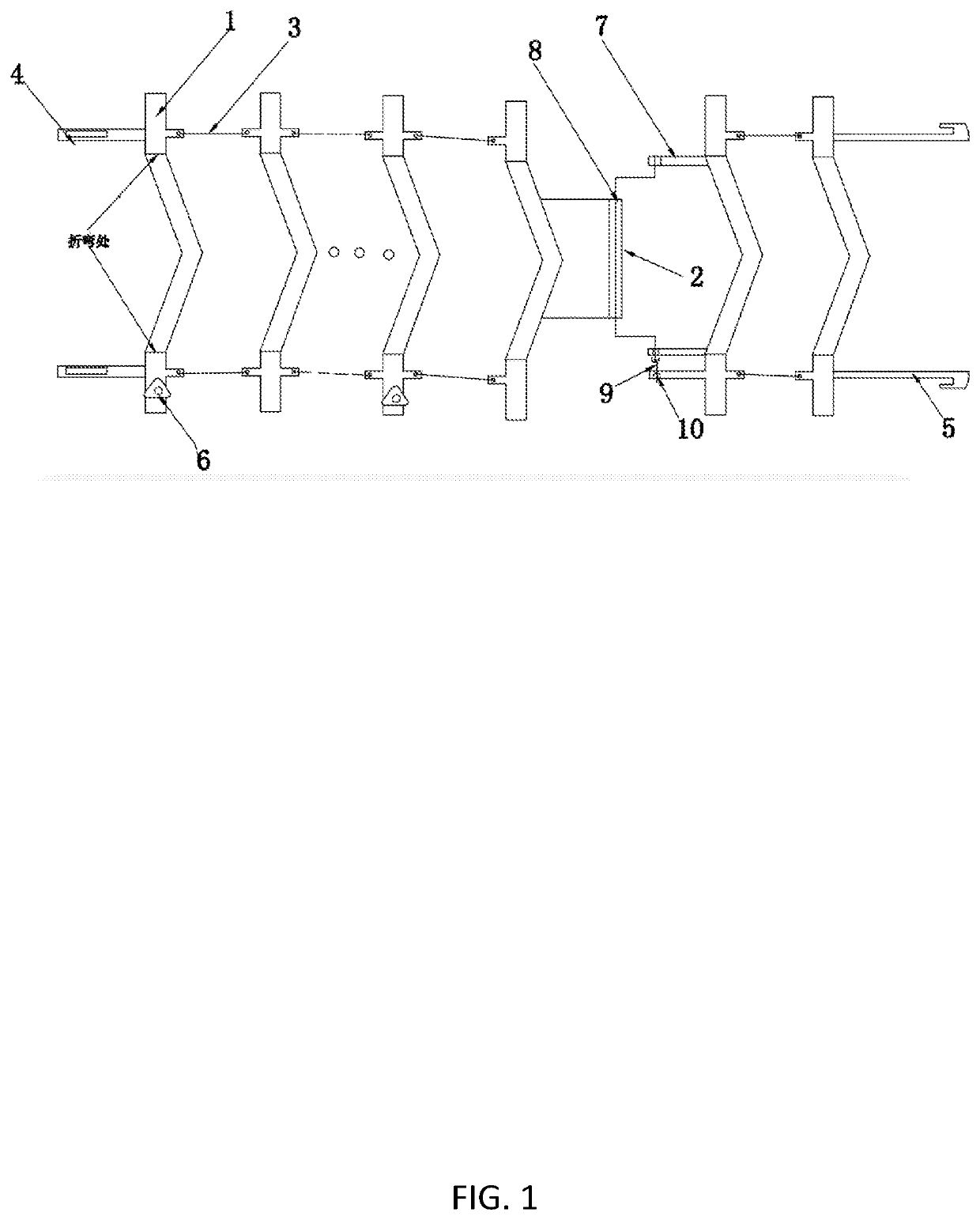
[0037]See FIGS. 1, 4, and 5.

[0038]An external tensioning anti-skid chain for an automobile. It comprises a number of similar-structured U-shaped anti-skid boards 1 and the tightening mechanism shown in FIG. 4 (depending on the location, the main connector parts vary slightly). The tightening mechanism can be crank mechanism, wire rope tensioning mechanism or CAM locking mechanism. In the implementation example we use crank mechanism as an illustrate. The crank mechanism comprises a crankshaft 2 and an operating handle 9, shown in FIG. 1. The bottom of the U-shaped anti-skid plate 1 in contact with the ground shall preferably be designed with a “chevron pointing” character grain structure, while other non-slip pattern structure is also acceptable. The two vertical sides of U-shaped anti-skid board 1 are attached to the inside and outside of the tire. Except for one side of the first and last U-shaped anti-skid plate 1 and one side of the U-shaped anti-skid plate mounted with cranksha...

implementation example 2

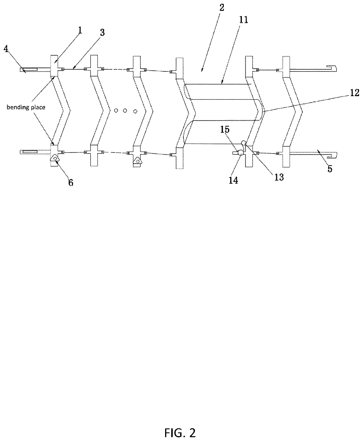
[0054]See FIG. 2.

[0055]The difference between this Example and Example 1 is that the tightening mechanism adopts the wire rope tightening mechanism. The mechanism used here is the wire rope tightening mechanism. One end of the wire rope 11 is attached to the bottom edge of a U-shaped anti-skid plate, and then enters the guide slot 12 of the adjacent U-shaped anti-skid plate and passes through the bottom edge of the two adjacent U-shaped anti-skid plate in an S-shape and then enters the guide ring 13 on a U-shaped anti-skid plate, and finally wounds on the ratchet 14. Turning the ratchet 14 can tighten the wire rope. Loosening the pawl 15 can reversely loosen the wire rope.

implementation example 3

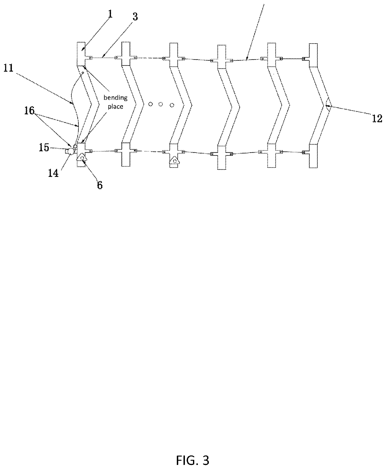
[0056]See FIGS. 3 and 4.

[0057]An external tensioning anti-skid chain for an automobile, which comprises multiple U-shaped anti-skid plates of the same structure 1 and a set of wire rope tightening mechanism 16. The two vertical sides of U-shaped anti-skid plate 1 are attached to the inside and outside of the tire. The first section (head section) and the last section (tail section) U-shaped anti-skid plates 1 are connected through the wire rope tightening mechanism 16. A manual screw plate 6 for mounting and positioning is attached to the lateral vertical side of one or two U-shaped anti-skid plates 1. The wire rope tightening mechanism 16 is composed of a wire rope 11, a ratchet wheel 14 and a ratchet claw 15. One end of the wire rope 11 is fixed on the inner bottom edge of U-shaped anti-skid plate 1. The other end is connected to the ratchet 14 by bypassing the guide slot 12 on the adjacent U-shaped anti-skid plate 1. When turning the ratchet 14 to tighten the wire rope 11 and rel...


PUM


Abstract

An external tensioning anti-skid chain system for an automobile, whose characteristics include a number of U-shaped anti-skid boards with the same structure and a set of tightening mechanisms. The two vertical edges of the U-shaped anti-skid plate are attached to the inside and outside of a tire. The first section and the last section of the U-shaped anti-skid plate are connected by a buckle structure. The tightening mechanism is installed between two adjacent U-shaped anti-skateboards, and the U-shaped anti-skid plates are mutually connected by connection rings. The anti-skid chain system has a simple structure, making installation and disassembly very easy.

Description

CROSS REFERENCE TO RELATED APPLICATIONS[0001]The present application claims priority to International Patent Application Serial No. PCT / CN2019 / 075093 filed 14 Feb. 2019, and to Chinese Patent Application Serial No. 201810399703.4 filed 28 Apr. 2018, both of which are hereby incorporated by reference in their entirety.BACKGROUND OF THE INVENTIONField of the Invention[0002]The invention relates to an automobile technology, in particular to an automobile anti-skid technology. Specifically, it is an external (including crankshaft and wire rope) anti-skid chain of an automobile which can be tensioned on the outside of the vehicle without having to extend the hand to the inside of the tire for operation.Description of Related Art[0003]As we all know, ordinary road surface is most suitable for tires. If the road surface is frozen, the adhesion of car tires to the ice must be greatly reduced. Serious problems will occur in the effective output of engine power, the maneuverability of automob...

Claims


Application Information

Patent Timeline
Patent Type & Authority Applications(United States)
IPC IPC(8): B60C27/10B60C27/06
CPCB60C27/10B60C27/068B60C27/066B60C27/14
Inventor ZHUANG, LE
Owner ZHUANG LE
Learn More