
Data transmission system

a data transmission system and data technology, applied in the field of data transmission systems, can solve the problems of mechanical and/or electrical failure of the gap, mechanical and/or electrical weakening of the drill string, and the introduction of an electrical gap into the drill string, etc., to achieve reliable and fast transmission of sensor data, without loss of performance or functionality.

Active Publication Date: 2021-02-11
ISODRILL INC
View PDF0 Cites 1 Cited by
  • Summary
  • Abstract
  • Description
  • Claims
  • Application Information

AI Technical Summary

Benefits of technology

The invention is a gap sub that uses insulating materials to provide a strong and reliable connection between two parts. It includes an outer sleeve, inner sleeve, insulating outer and inner washers, and an insulating spider. The gap sub is designed to transfer loads in different directions, making it stronger than traditional insulated gap collars. It allows for reliable and fast transmission of sensor data to the surface while keeping the connection secure. The upper and lower parts of the gap sub can be swapped without losing performance.

Problems solved by technology

However, one drawback of conventional EM data transmission systems is that introducing an electrical gap into the drill string mechanically weakens the drill string, as the electrical gap is often created by sandwiching insulating materials between two separate metallic sections of one or more drill collars.
During operation, the insulating material may be subject to torsional, compressional, and cyclical bending stresses under load.
In some applications, low modulus insulating materials can plastically deform over time, while high modulus insulating materials may fracture, with both failures causing mechanical and / or electrical failure of the gap.
Further, EM data transmission systems may transmit at a low broadcast signal strength when operated on batteries, causing susceptibility to electrical noise that interferes with the detection and demodulation of the surface signal.
Compounded with mechanical and / or electrical failure of the gap, as described above, battery operation can result in a severe reduction in transmitted signal strength.

Method used


Image

  • Data transmission system
  • Data transmission system
  • Data transmission system

Examples


Embodiment Construction

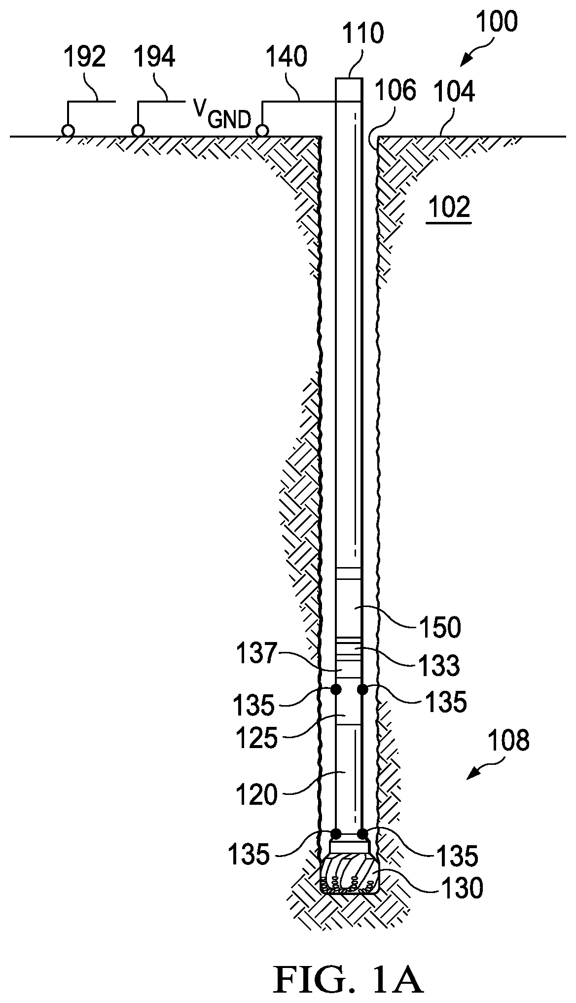
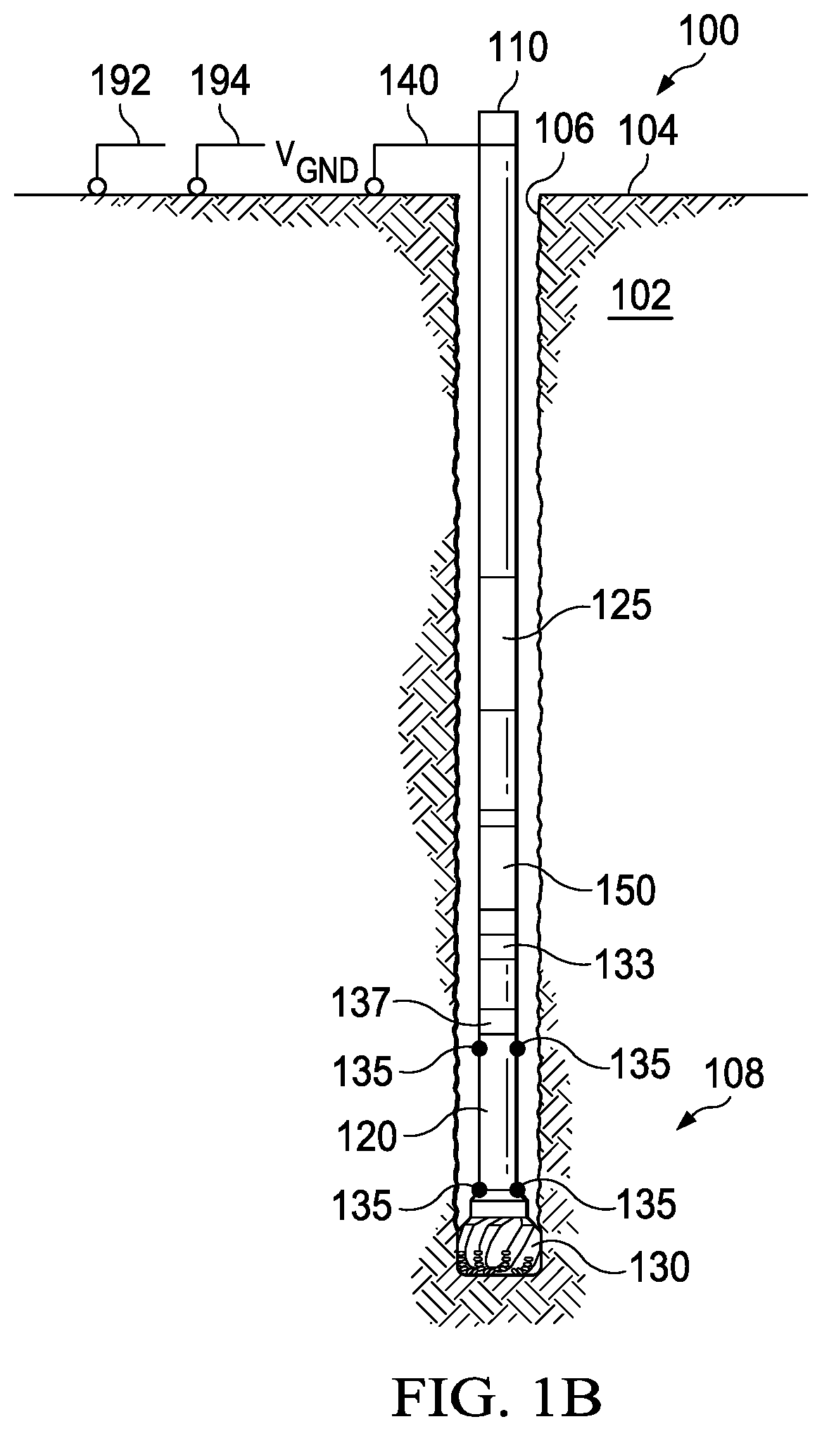
[0016]FIG. 1A and 1B are schematic views of a drilling system 100. In the depicted example, the drilling system 100 can be utilized to drill a wellbore 106 through a formation 102 and can facilitate the transmission of telemetry information from a downhole location 108 to a surface location 104 for logging and real-time control of drilling operations.

[0017]As illustrated, a drill bit 130 coupled to a downhole end of a drill string 110 can be rotated within the formation 102 to form the wellbore 106. During the drilling operation, the drill string 110 can extend within the wellbore 106 from the surface location 104 to the downhole location 108. As can be appreciated, the drilling system 100 can form vertical wells, horizontal wells, lateral wells, and / or utilize directional drilling techniques.

[0018]In some embodiments, various sensors 135 disposed within or along the drill string 110 can be used to measure and observe parameters at the drill bit 130 or generally at the downhole loca...


PUM


Abstract

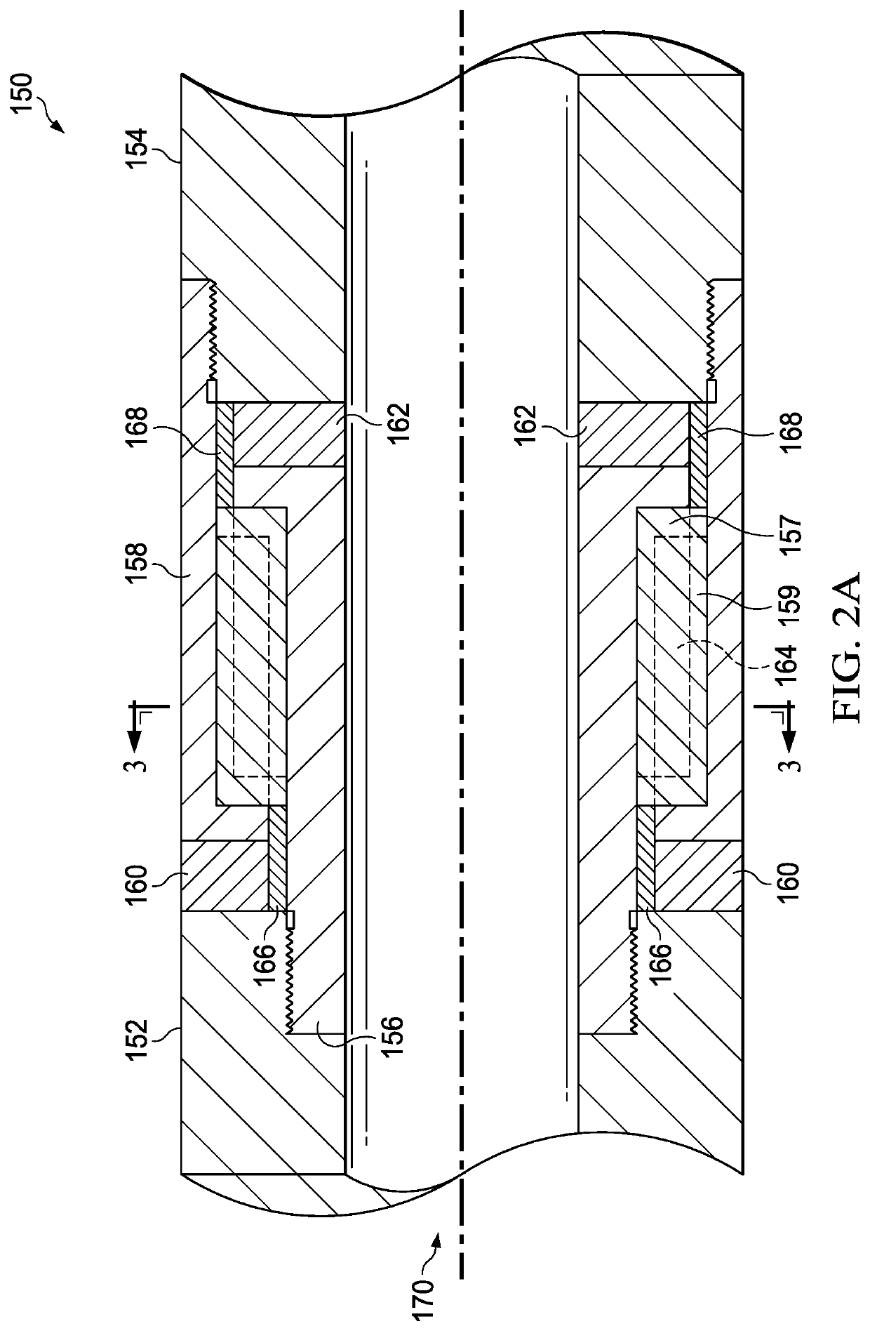
A gap sub uses a plurality of insulating members in conjunction with at least two metallic members to effect a mechanically and electrically robust configuration. The gap sub includes an upper end portion, a lower end portion, an outer sleeve, an inner sleeve, an insulating outer washer, an insulating inner washer, and an insulating spider. The insulating outer washer is configured to transfer a first axial load between the upper end portion and the outer sleeve. The insulating inner washer is configured to transfer a second axial load between the inner sleeve and the lower end portion. The insulating spider is configured to transfer a torsional load between outer sleeve and the inner sleeve. Because the insulating washers are utilized to transfer axial loads and the insulating spider is utilized to transfer torsional loads, each insulator may be manufactured so that the strongest axis of the material can be optimally and advantageously oriented to be coincident with the forces applied to each insulator, thereby making the gap sub more mechanically robust than a conventional insulated gap collar while permitting reliable and fast transmission of sensor data to the surface.

Description

TECHNICAL FIELD[0001]The present disclosure relates generally to data transmission systems, and more particularly, to electromagnetic (EM) data transmission systems for use within wellbores.BACKGROUND[0002]Wells are drilled to facilitate the extraction of hydrocarbons from a formation. During the drilling of a well, various drilling parameters can be monitored to adjust and optimize drilling operations. For example, sensors may be utilized to monitor parameters for steering a drill bit, measurements for the optimization of drilling efficiency, formation electrical resistivity, downhole pressure, direction and inclination of the drill bit, torque on bit, weight on bit, etc. During operation, sensor readings or data from the downhole sensors can be transmitted to the surface for monitoring, analysis, decision-making, and otherwise controlling drilling operations.[0003]Drilling systems can transmit data from downhole sensors to a surface location for the above-mentioned purposes. For e...

Claims


Application Information

Patent Timeline
IPC IPC(8): E21B47/13E21B17/02E21B17/046
CPCE21B47/13E21B17/042E21B17/046E21B17/0285E21B47/12
Inventor BARGACH, SAADBONNER, STEPHEN D.NAGULA, MADHUSUDHAN
Owner ISODRILL INC
Learn More