The remote locking method of the site standby automatic switching device

A technology for self-switching and station preparation, applied in circuit devices, electrical components, information technology support systems, etc., can solve problems such as limitation, cumbersome transformation, and difficulty in large-scale promotion, and achieve stable, reliable and rapid signal transmission. , the effect of low cost

Active Publication Date: 2021-11-30
STATE GRID HUNAN ELECTRIC POWER +1
View PDF4 Cites 0 Cited by
  • Summary
  • Abstract
  • Description
  • Claims
  • Application Information

AI Technical Summary

Problems solved by technology

Blocking is realized through regional backup automatic switching, and the regional control center sends a pause or blocking command to control the action behavior of station backup automatic switching, thereby realizing the main and auxiliary control mode of regional backup automatic switching and site backup automatic switching. The transformation often involves other parts of the power grid For protection or safety automatic devices, special channels need to be added, the transformation is cumbersome, and it is difficult to promote on a large scale
However, the wide-area standby automatic switching control system based on the EMS system establishes a wide-area standby automatic switching model at the main dispatching station, and uses EMS real-time telemetry information to realize logical judgment. The strategy and verification method of the backup auto-injection cannot solve the problem of remote blocking of the backup auto-injection for the time being.

Method used


Image

  • The remote locking method of the site standby automatic switching device

Examples


Embodiment Construction

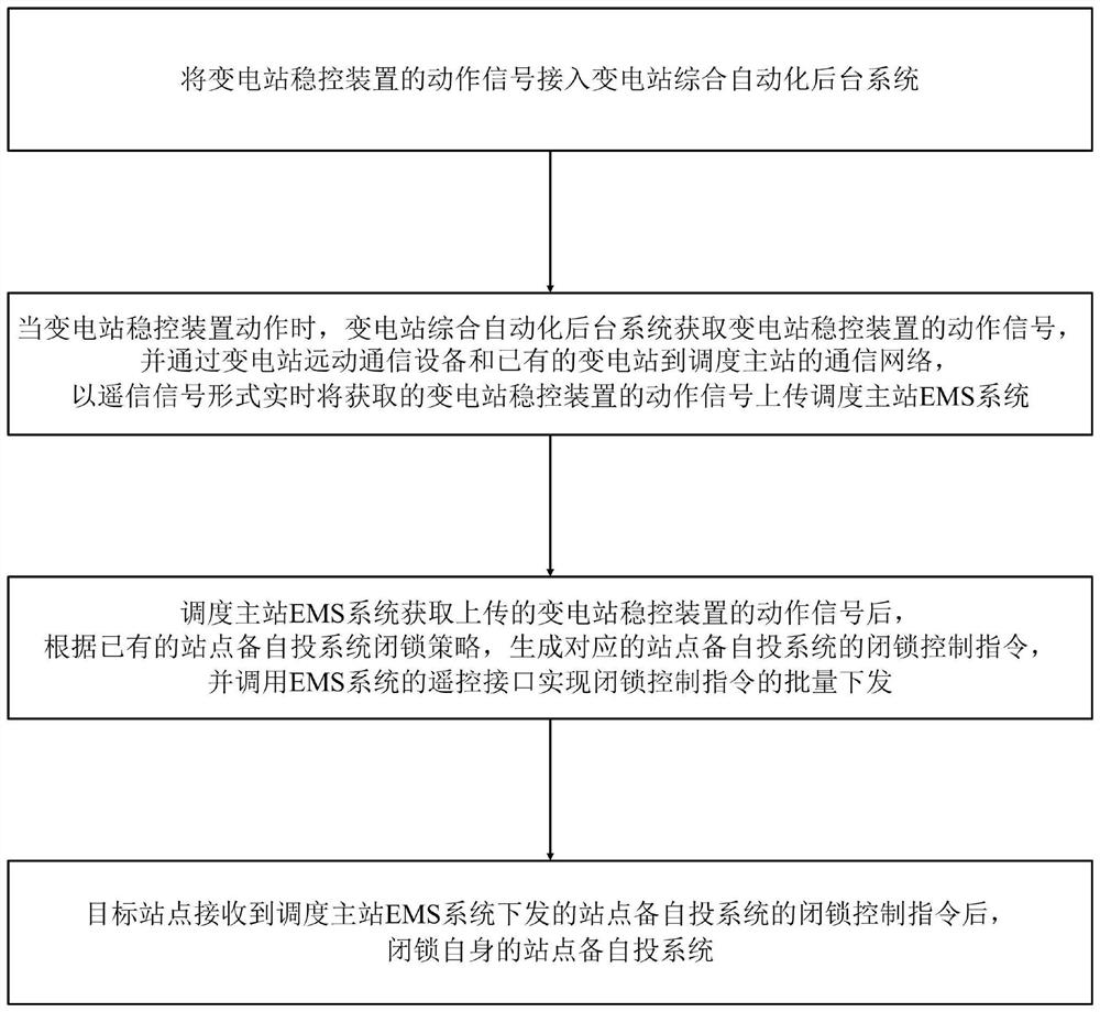
[0018] Such as figure 1 Shown is the schematic flow chart of the method of the present invention: the remote locking method of the site standby automatic switch system of the site standby automatic switch device provided by the present invention comprises the following steps:

[0019] S1. Connect the action signal of the substation stability control device to the substation comprehensive automation background system;

[0020] S2. When the substation stability control device operates, the substation integrated automation background system obtains the action signal of the substation stability control device, and through the substation remote communication equipment and the existing communication network from the substation to the dispatching master station, real-time in the form of remote signaling Upload the obtained action signal of the substation stability control device to the EMS system of the dispatching master station;

[0021] S3. After obtaining the action signal of th...


PUM


Abstract

The invention discloses a remote locking method for a site backup self-injection device, which includes connecting the action signal of the substation stability control device to the substation comprehensive automation background system; Real-time upload to the EMS system of the dispatching master station; after receiving the signal, the EMS system of the dispatching master station generates a blocking control command according to the blocking strategy of the site backup self-injection device and calls the remote control interface to realize the batch delivery of the blocking control command; the target station receives the blocking control command and blocks Its own site is equipped with a self-injection device. The invention realizes the real-time monitoring, acquisition and uploading of the action signal of the substation stability control device, as well as the remote locking and monitoring of the station standby self-injection device. The advanced grid hardware and software system realizes the stable, reliable and rapid transmission of signals, and the signal transmission is stable, reliable and safe.

Description

technical field [0001] The invention specifically relates to a remote locking method of a station equipment self-injection device. Background technique [0002] With the continuous advancement of UHV AC and DC construction, long-distance high-power transmission power becomes possible. Affected by factors such as the relatively weak grid structure in the early stage of UHV grid construction, the lagging construction of supporting power sources, and the bottleneck of grid security and stability constraints, UHV DC blocking faults will cause large-scale power flow shifts, which will have a greater impact on the receiving end grid. In order to ensure the overall safety and stability of the receiving-end power grid and ensure the efficiency of UHV DC transmission, a large-scale stable control load shedding system needs to be built simultaneously in the surrounding area. As a common safety automatic device for the power grid, the standby automatic switching device can significant...

Claims


Application Information

Patent Timeline
Patent Type & Authority Patents(China)
IPC IPC(8): H02J13/00
CPCY02E60/00Y04S10/16
Inventor 李琳许霖王哲赵子鋆吴东琳
Owner STATE GRID HUNAN ELECTRIC POWER
Why Eureka
Try Eureka