Tray device and electronic device having the same

a technology of electronic devices and trays, which is applied in the direction of instruments, conveying record carriers, substation equipment, etc., can solve the problems of difficult design of antenna radiators, achieve the effect of improving the performance of the peripheral electric structure, and reducing the mounting space of the tray

Active Publication Date: 2021-02-11
SAMSUNG ELECTRONICS CO LTD
View PDF0 Cites 1 Cited by
  • Summary
  • Abstract
  • Description
  • Claims
  • Application Information

AI Technical Summary

Benefits of technology

The patent text describes a tray device that helps to make electronic devices slimmer and more compact by reducing the space needed for the tray to mount. This improves the device's overall performance and contributes to its overall slimming design.

Problems solved by technology

However, in the tray device, because the eject bars are disposed side by side outside the tray socket, the tray cover of the tray has to provide an additional space for a pin insertion hole for receiving an ejecting pin, which may be a retrogressive problem in slimming of the electronic device.
Moreover, in a structure of an electronic device in which at least some of side members of a conductive material are used as the antenna, a mounting space occupied by the tray may cause difficulty in designing an antenna radiator.

Method used


Image

  • Tray device and electronic device having the same
  • Tray device and electronic device having the same
  • Tray device and electronic device having the same

Examples


Embodiment Construction

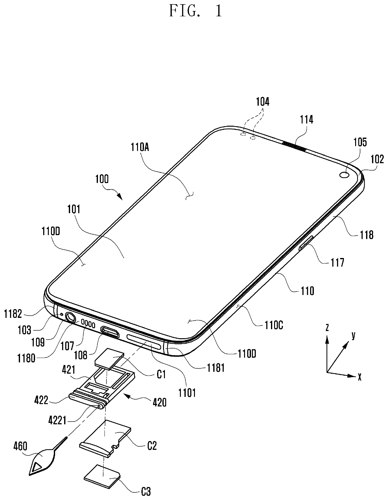
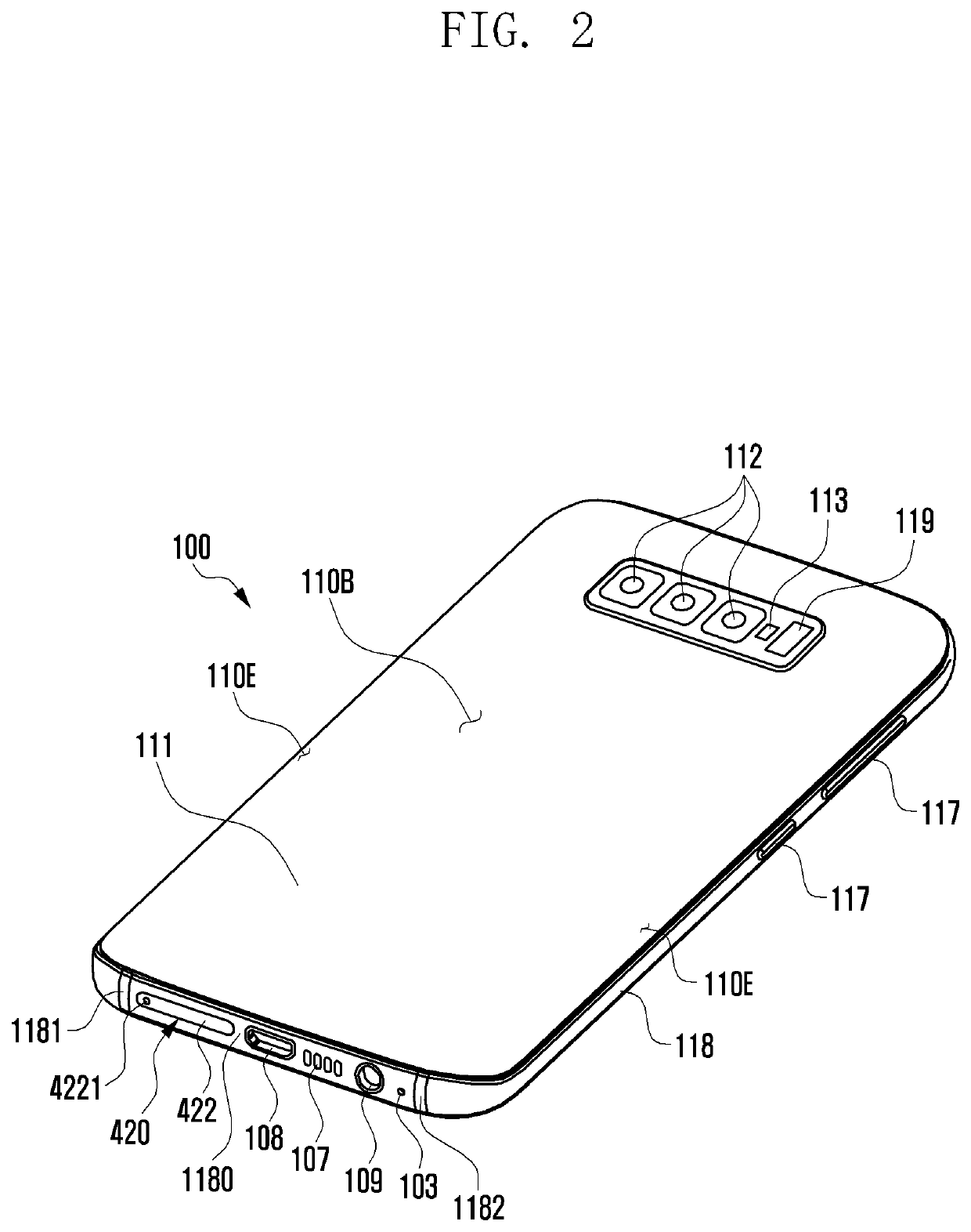
[0027]FIG. 1 is a front perspective view illustrating an example mobile electronic device according to an embodiment of the disclosure, and FIG. 2 is a rear perspective view illustrating the mobile electronic device shown in FIG. 1 according to an embodiment of the disclosure.

[0028]Referring to FIGS. 1 and 2, a mobile electronic device 100 may include a housing 110 that includes a first surface (or front surface) 110A, a second surface (or rear surface) 110B, and a lateral surface 110C that surrounds a space between the first surface 110A and the second surface 110B. The housing 110 may refer to a structure that forms a part of the first surface 110A, the second surface 110B, and the lateral surface 110C. The first surface 110A may be formed of a front plate 102 (e.g., a glass plate or polymer plate coated with a variety of coating layers) at least a part of which is substantially transparent. The second surface 110B may be formed of a rear plate 111 which is substantially opaque. T...


PUM


Abstract

According to various embodiments, an electronic device may include: a housing including an opening connected to an internal space of the electronic device; a tray socket connected to outside the electronic device through the opening in the internal space and including a tray reception space; a tray configured to be inserted into the tray reception space, wherein the tray includes a tray body including at least one space configured to receive at least one external component; and a tray cover including a pin insertion hole configured to guide a tray ejecting pin to the opening; an eject bar movably disposed in a tray mounting direction or ejecting direction in the tray reception space and facing the pin insertion hole; and a rotation lever configured to press the tray in the ejection direction based on pressing of the eject bar in the tray reception space, wherein the eject bar is disposed at a position at least partially overlapping the tray body when viewed from above the tray socket.

Description

CROSS-REFERENCE TO RELATED APPLICATION[0001]This application is based on and claims priority under 35 U.S.C. § 119 to Korean Patent Application No. 10-2019-0096609, filed on Aug. 8, 2019, in the Korean Intellectual Property Office, the disclosure of which is incorporated by reference herein in its entirety.BACKGROUNDField[0002]The disclosure relates to a tray device and an electronic device including the same.Description of Related Art[0003]In recent years, portable electronic devices have been diversified in function, while portable electronic devices with favorable portability may have higher competitiveness. For example, an electronic device that is slimmer, lighter, and shorter among electronic devices having the same function may be preferred. Therefore, electronic device manufacturers are racing to develop devices that are slimmer, lighter, and shorter than other products while having the same or better function.[0004]As part of this trend, electronic devices may include remov...

Claims


Application Information

Patent Timeline
IPC IPC(8): G06K7/00G06K13/08H04B1/3818H04M1/02
CPCG06K7/003G06K13/0831H04M1/0277H04B1/3818H04M1/0274G06K13/0825G06K7/0043G06K7/0073G06K13/08G06K13/0812H04M1/026
Inventor HEO, JOONKIM, YONGHWASUNG, MINYOUNG
Owner SAMSUNG ELECTRONICS CO LTD
Why Eureka
Try Eureka