Inductor component

a technology of components and components, applied in the manufacture of inductances, transformers/inductances coils/windings/connections, inductances/transformers/magnets, etc., can solve the problems of inefficient heat dissipation outside the inductor component, and achieve the effect of excellent heat dissipation effect and easy improvement of direction distinguishability

Active Publication Date: 2021-02-11
MURATA MFG CO LTD
View PDF13 Cites 2 Cited by
  • Summary
  • Abstract
  • Description
  • Claims
  • Application Information

AI Technical Summary

Benefits of technology

[0008]Accordingly, the present disclosure provides an inductor component having an exc

Problems solved by technology

Consequently, for example, during use of the inductor component, the direction-distinguishing layer disposed between the element assembly and the outside of the inductor

Method used


Image

  • Inductor component
  • Inductor component
  • Inductor component

Examples


first embodiment

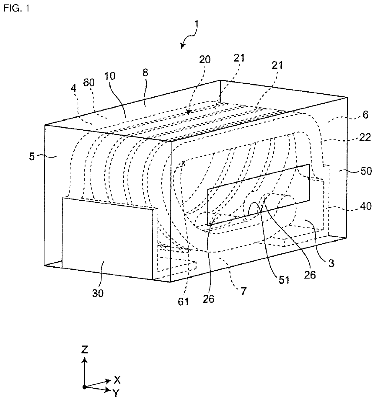
[0021]FIG. 1 is a transparent perspective view showing a first embodiment of an inductor component. As shown in FIG. 1, the inductor component 1 includes an element assembly 10, a first direction-distinguishing layer 50 having a first cavity 51 at which part of the element assembly 10 is exposed, and a second direction-distinguishing layer 60 having a second cavity 61 at which part of the element assembly 10 is exposed. The inductor component 1 further includes a spiral coil 20 disposed inside the element assembly 10 and a first outer electrode 30 and a second outer electrode 40 that are electrically coupled to the coil 20 disposed in the element assembly 10.

[0022]The inductor component 1 (first outer electrode 30 and second outer electrode 40) is electrically coupled to wiring lines of a circuit board (not shown) by, for example, solder (not shown). The inductor component 1 is used as, for example, an impedance matching coil (matching coil) of a high-frequency circuit and is used f...

second embodiment

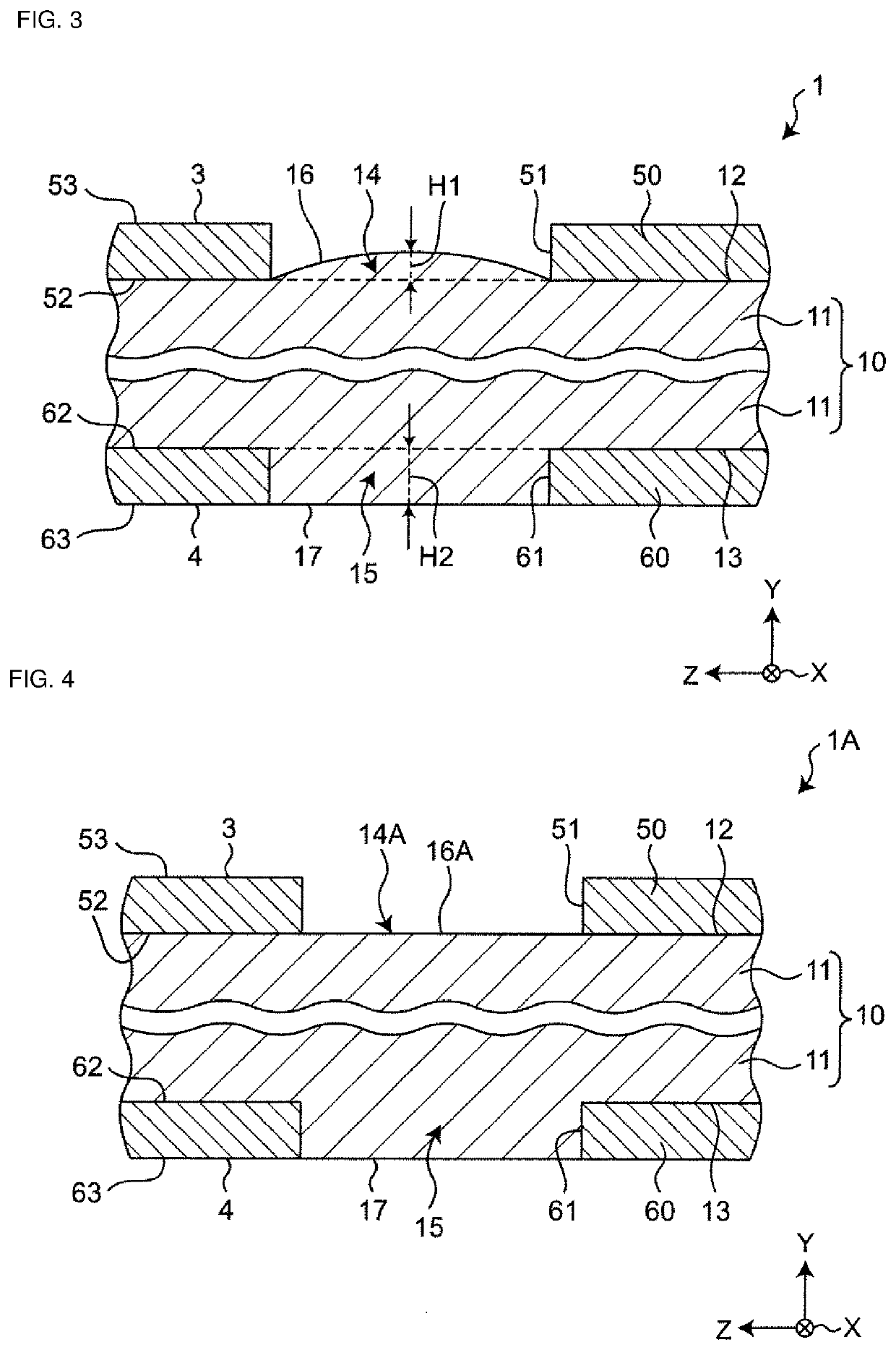
[0074]FIG. 4 is a magnified sectional view showing a second embodiment of the inductor component. FIG. 4 shows a modified example of the first embodiment shown in FIG. 3. The second embodiment is different from the first embodiment in that an exposed surface 16A of a first exposed portion 14A is flush with the third surface 52 of the first direction-distinguishing layer 50. The configuration related to this difference will be described below. In the second embodiment, the same references as in the first embodiment indicate the same configurations as in the first embodiment, and explanations thereof are omitted.

[0075]Configuration

[0076]As shown in FIG. 4, in the inductor component 1A of the second embodiment, the exposed surface 16A of the first exposed portion 14A is flush with the third surface 52 of the first direction-distinguishing layer 50, and the exposed surface 17 of the second exposed portion 15 is flush with the sixth surface 63 of the second direction-distinguishing layer...

third embodiment

[0082]FIG. 5 is a magnified sectional view showing a third embodiment of the inductor component. FIG. 5 shows a modified example of the first embodiment shown in FIG. 3. The third embodiment is different from the second embodiment in the cross-sectional shape of a first cavity 51B. The configuration related to this difference will be described below. In the third embodiment, the same references as in the first embodiment and the second embodiment indicate the same configurations as in the first embodiment and the second embodiment, and explanations thereof are omitted.

[0083]Configuration

[0084]As shown in FIG. 5, in the inductor component 1B of the third embodiment, the inner surface of the first cavity 51B is inclined such that the inner diameter of the first cavity 51B increases from the third surface 52 of the first direction-distinguishing layer 50 toward the fourth surface 53. That is, the first cavity 51B has a tapered shape.

[0085]Since the inner surface of the first cavity 51B...


PUM


Abstract

An inductor component includes an element assembly having a first surface and a second surface located opposite to the first surface, a first direction-distinguishing layer disposed on the first surface, and a second direction-distinguishing layer disposed on the second surface. The first direction-distinguishing layer has a first cavity passing through in the thickness direction. The second direction-distinguishing layer has a second cavity passing through in the thickness direction. The element assembly has a first exposed portion that is part of the element assembly and that is exposed in the first cavity and has a second exposed portion that is part of the element assembly and that is exposed in the second cavity. The first amount of protrusion of the first exposed portion protruding in the thickness direction is less than the second amount of protrusion of the second exposed portion protruding in the thickness direction.

Description

CROSS-REFERENCE TO RELATED APPLICATION[0001]This application claims benefit of priority to Japanese Patent Application No. 2019-145556, filed Aug. 7, 2019, the entire content of which is incorporated herein by reference.BACKGROUNDTechnical Field[0002]The present disclosure relates to an inductor component.Background Art[0003]An inductor component is described in Japanese Unexamined Patent Application Publication No. 2011-14940. This inductor component includes an element assembly having a first end surface and a second end surface located opposite to the first end surface and outer electrodes disposed on the first end surface and the second end surface. The element assembly further has a first side surface (first surface) located perpendicularly to the first end surface and the second end surface, and a second side surface (second surface) located opposite to the first side surface, a third side surface located perpendicularly to the first end surface, the second end surface, the fi...

Claims


Application Information

Patent Timeline
IPC IPC(8): H01F27/32H01F27/02H01F41/12
CPCH01F27/323H01F41/122H01F27/02H01F17/0013H01F27/025H01F27/085H01F2017/004
Inventor SHIMODA, YUTATAJIMA, SHINYANAKASHIMA, YASUNARI
Owner MURATA MFG CO LTD
Why Eureka
Try Eureka