

Bonding structure of dissimilar metal members and precursor thereof
- Summary
- Abstract
- Description
- Claims
- Application Information
AI Technical Summary
Benefits of technology
Problems solved by technology
Method used
Image

Examples
first embodiment
[0045]Hereinafter, a first embodiment of the present invention will be appropriately described with reference to FIGS. 1 to 3. Further, the embodiment described below is an aspect of the present invention, the present invention is not limited to the embodiment described below, and various modifications may be made without departing from the scope of the present invention.
[0046]A bonding structure according to the first embodiment of the present invention will be described with reference to FIG. 1.
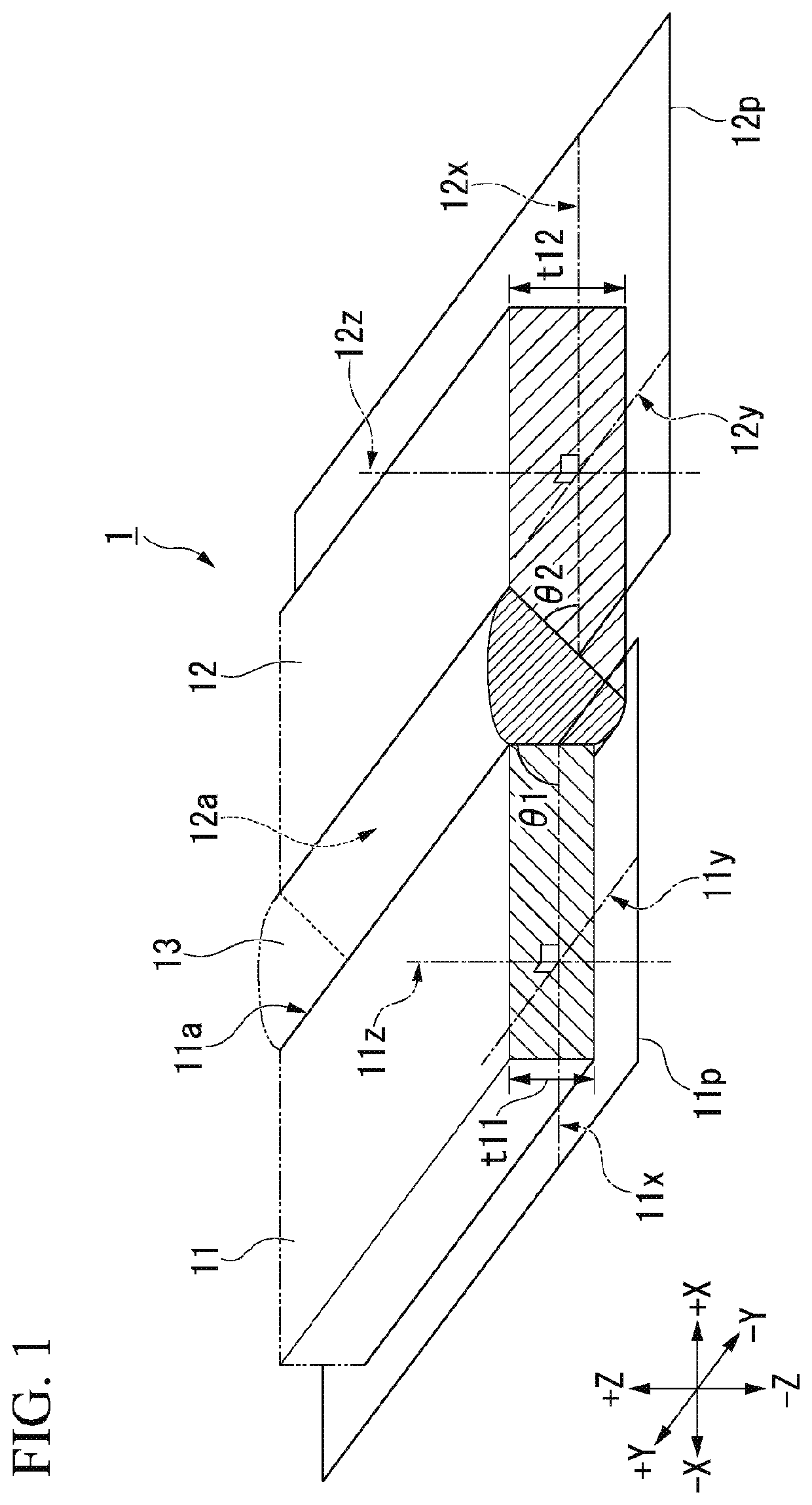
[0047]A schematic configuration of the bonding structure according to the first embodiment of the present invention is shown in FIG. 1.
[0048]A bonding structure 1 shown in FIG. 1 includes a plate-shaped first metal member 11, a plate-shaped second metal member 12, and a brazing filler metal 13.
[0049]The second metal member 12 is formed of a material different from the first metal member 11. The brazing filler metal 13 is bonded to a bonding end surface 11 a of the first metal member 11 and ...
second embodiment
[0093]A schematic configuration of a bonding structure according to a second embodiment of the present invention is shown in FIG. 4.
[0094]The bonding structure 101 shown in FIG. 4 includes a plate-shaped first metal member 111, a plate-shaped second metal member 112 and a brazing filler metal 113.
[0095]The second metal member 112 is formed of a material different from the first metal member 111.
[0096]The brazing filler metal 113 is bonded to a bonding end surface 111a of the first metal member 111 and a bonding end surface 112a of the second metal member 112.
[0097]Further, the bonding structure 101 satisfies any one or both of the following conditions (1) and (2).
[0098](1) At least a part of the bonding end surface 111a of the first metal member 111 in the thickness direction of the first metal member 111 is an inclined surface inclined with respect to a plane 111p perpendicular to the thickness direction of the first metal member 111.
[0099](2) At least a part of the bonding end sur...
example 11
(Fabrication of Specimen)
[0146]An Al plate 411 (an Al—Mg—Si-based alloy plate, width W1=40 mm, length L1=120 mm, thickness T1=1.0 mm, an angle 45° formed between the bonding end surface and the plane perpendicular to the thickness direction), and a Fe plate 412 (a hot-dipped aluminum plated steel plate, width W2=50 mm, length L2=120 mm, thickness T2=1.8 mm, an angle 90° formed between the bonding end surface and the plane perpendicular to the thickness direction) were prepared. Similar to Comparative Example 1, a bonding structure 401 shown in FIG. 8 was manufactured using them. The Al plate 411 and the Fe plate 412 were bonded via an Al brazing filler metal 413. Similarly, a bonding member was additionally fabricated, and three specimens were fabricated in total.
(Strength Test)
[0147]Similar to Comparative Example 1, a breaking load and an arithmetical mean (mean value), and mean tensile strength of each specimen were obtained using the bonding structure 401 shown in FIG. 8. Test re...
PUM
| Property | Measurement | Unit |
|---|---|---|
| Pressure | aaaaa | aaaaa |
| Angle | aaaaa | aaaaa |
| Angle | aaaaa | aaaaa |
Abstract
Description
Claims
Application Information