

Insulation assembly
A technology for insulating components and insulating umbrellas, which is applied to insulators, insulators, rubber insulators, etc., can solve the problems of reducing the electrical performance of insulating components, increasing the manufacturing cost of insulating components, and high cost of metal flanges, improving electric field distribution, and extending creepage. Distance and dry arc distance, good bonding strength
- Summary
- Abstract
- Description
- Claims
- Application Information
AI Technical Summary
Problems solved by technology
Method used
Image

Examples
no. 1 example
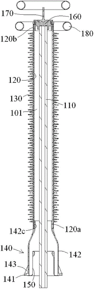
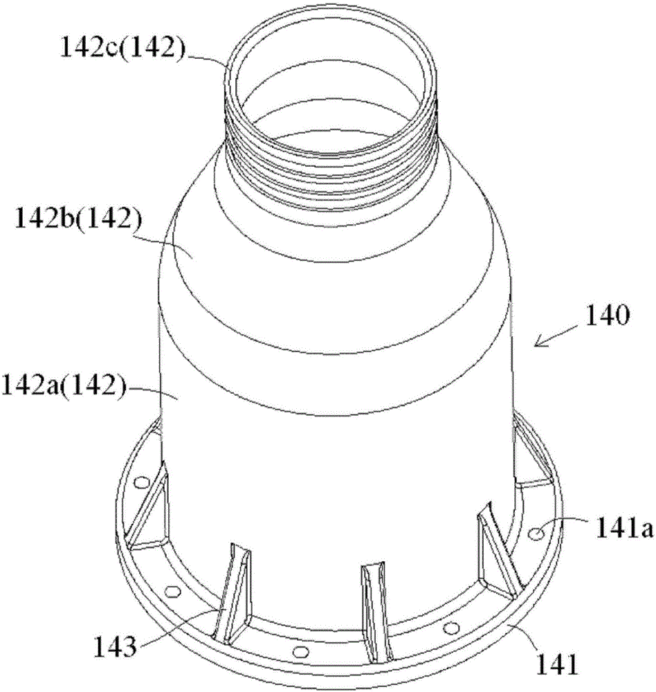
[0057] figure 1 A longitudinal sectional view showing an insulating assembly according to a first exemplary embodiment of the present invention; figure 2 show figure 1 A three-dimensional schematic diagram of the insulating base 140 of the insulating assembly in FIG.
[0058] Such as figure 1 and figure 2 As shown, in the illustrated embodiment, the insulation assembly mainly includes an insulation sleeve 120 , an insulation umbrella group 130 and an insulation base 140 . The insulating sleeve 120 has a first end 120a and a second end 120b opposite to the first end 120a. The insulating umbrella group 130 is formed on the outer wall of the insulating sleeve 120 . The insulating base 140 is connected to the first end 120 a of the insulating sleeve 120 .
[0059] In one embodiment of the present invention, the insulating umbrella group 130 may be a silicone rubber umbrella group molded on the outer wall of the insulating sleeve 120 . The insulating sleeve 120 may be a wi...
no. 2 example
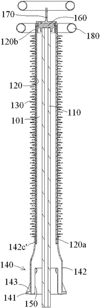
[0092] Figure 4 A longitudinal sectional view showing an insulating assembly according to a second exemplary embodiment of the present invention; Figure 5 show Figure 4 An enlarged partial schematic of the insulation assembly shown; and Figure 6 show Figure 4 A three-dimensional schematic diagram of the insulating base 240 of the insulating assembly shown.
[0093] Such as Figure 4 , Figure 5 and Figure 6 As shown, in the illustrated embodiment, the insulation assembly mainly includes an insulation sleeve 220 , an insulation umbrella group 230 and an insulation base 240 . The insulating sleeve 220 has a first end 220a and a second end 220b opposite to the first end 220a. The insulating umbrella group 230 is formed on the outer wall of the insulating sleeve 220 . The insulating base 240 is connected to the first end 220 a of the insulating sleeve 220 .
[0094] In one embodiment of the present invention, the insulating umbrella group 230 may be a silicone rubbe...
PUM
| Property | Measurement | Unit |
|---|---|---|
| Length | aaaaa | aaaaa |
| Length | aaaaa | aaaaa |
| Length | aaaaa | aaaaa |
Abstract
Description
Claims
Application Information