
Rotary engine

Active Publication Date: 2021-02-25
LG ELECTRONICS INC
View PDF0 Cites 1 Cited by
  • Summary
  • Abstract
  • Description
  • Claims
  • Application Information

AI Technical Summary

Benefits of technology

The present invention relates to a rotary engine that can reduce exhaust gas interference, improve fuel efficiency, and reduce damage to the engine. The engine has a structure that allows for smooth exhaust gas discharge in the second half of the exhaust stroke. Additionally, the engine uses a unique crankshaft design that helps it operate stably even at high loads. This design reduces the number of components and improves assembly, resulting in a more efficient and reliable rotary engine.

Problems solved by technology

However, when the rotor and the apex seal are thermally deformed due to heat generated by combustion, interference between the intake port or the exhaust port provided in the sidewall of the rotor and the apex seal may occur, and thus the rotor and the apex seal may be damaged.
In the structure, an overlap section where both the intake port and the exhaust port are opened may occur in an intake stroke of the engine, and in this case, there is a problem in that the exhaust gas is suctioned together with mixed air of fuel and air in the intake stroke.
When the exhaust gas in the intake stroke is mixed, fuel and air are insufficient, and thus a problem that output of the engine is reduced occurs.

Method used


Image

  • Rotary engine
  • Rotary engine
  • Rotary engine

Examples


first embodiment

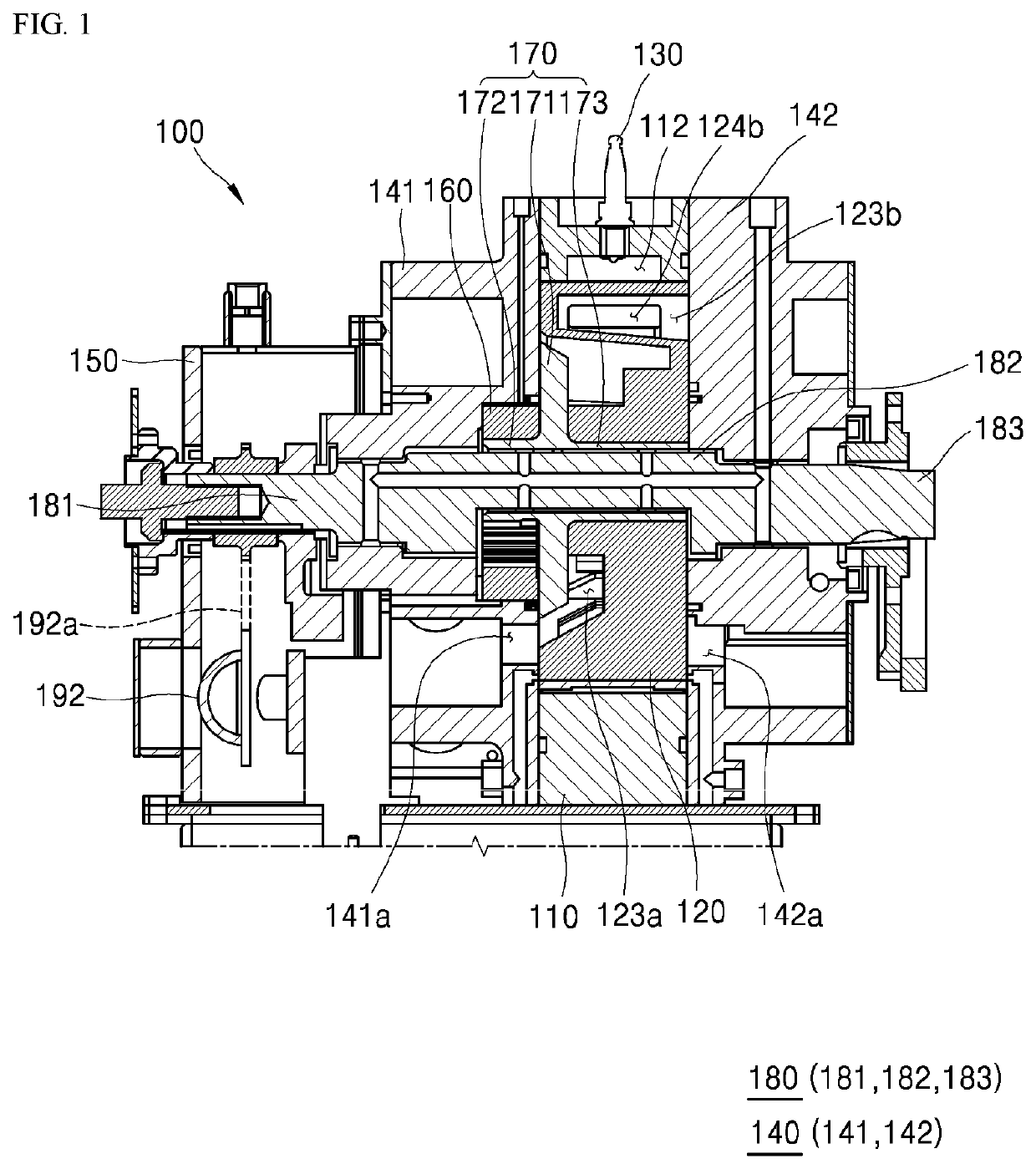
[0136]Referring to FIGS. 17 and 19, in the first embodiment, when the angle of the crankshaft is 690° to 720° in the exhaust stroke, it can be seen that the exhaust storage part 123b-1 and the exhaust hole 142a communicate with each other.

[0137]In other words, in a section from 540° to 720° of the exhaust stroke, although the exhaust storage part 123b and the exhaust hole 142a may not communicate with each other and thus the exhaust gas may not be smoothly exhausted even when the exhaust port is opened in a range in which the rotation angle of the crankshaft is 690° to 720° in the case of the comparative example in FIGS. 16 and 18, since the exhaust port is opened and thus the exhaust storage part 123b-1 and the exhaust hole 142a communicate with each other even in the range in which the rotation angle of the crankshaft is 690° to 720° in the case of the first embodiment in FIGS. 17 and 19, the exhaust storage part and the exhaust hole may communicate with each other in an entire an...

second embodiment

[0143]FIG. 22 is a perspective view illustrating an intake port of a rotor according to the present invention, and FIG. 23 is a view for describing contact between the intake port and an apex seal of the rotor when the rotor in FIG. 22 rotates in the counterclockwise direction.

[0144]As shown in the drawing, in the rotor according to the second embodiment of the present invention, an intake port 124c is provided with inclined surfaces 124c_1 and 124c_2 in surfaces formed in a direction parallel to the apex seal 117.

[0145]When the rotor 120 rotates in the counterclockwise direction, the apex seal 117 enters the intake port 124c by passing through the first surface 124c_1. When the rotor 120 passes through the first surface 124_1, the apex seal 117 which corresponds to the inside of the intake port 124c is not supported and is spaced apart, and thus may protrude into the intake port 124c due to an elastic force and thermal deformation. Further, when the apex seal 117 reaches the second...

third embodiment

[0154]In the present invention, an intake port 124c′ of the rotor 120 is provided with a guide surface 124g which divides the intake port 124c′ in a thickness direction of the rotor.

[0155]The intake port 124c′ formed in the side surface of the rotor 120 is formed to suction the mixed air by entering the stroke chamber according to the rotation of the crankshaft, and a position according to the rotation direction of the rotor is determined according to setting of an intake start angle and an intake end angle.

[0156]A size of the intake port 124c′ in the thickness direction of the rotor 120 is not related to the intake start angle and the intake end angle.

[0157]Accordingly, generally, the size of the intake port 124c′ in the thickness direction of the rotor is determined to be capable of maximally securing an opening area, and securing the rigidity of the rotor 120.

[0158]However, when the size of the intake port 124c′ in the thickness direction of the rotor increases, a section protrud...


PUM


Abstract

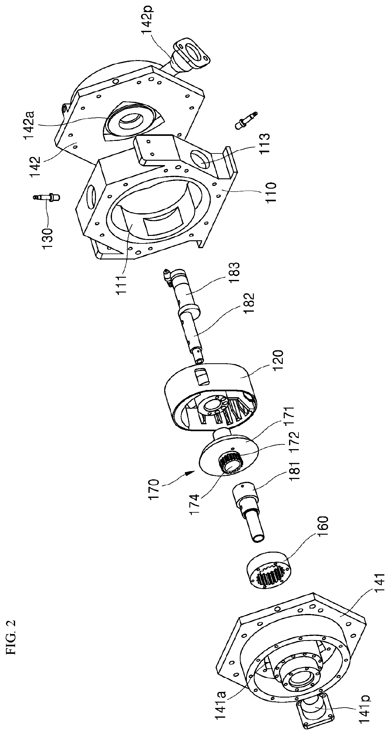
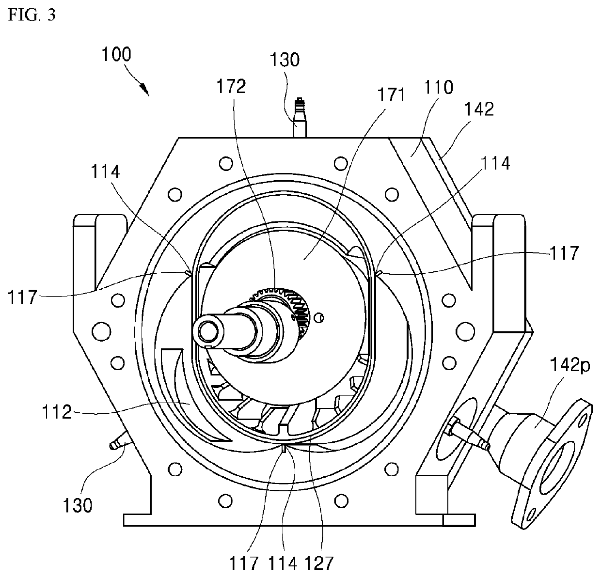
The present invention provides a rotary engine comprising: a housing provided with three lobe accommodation parts; a rotor which is provided with two lobes continuously accommodated in the lobe accommodation parts, has an intake storage part communicating with an intake port provided on the front surface-side, and has an exhaust storage part communicating with an exhaust port provided on the rear surface-side; an intake-side housing cover provided with an intake hole communicating with the intake storage part; an exhaust-side housing cover provided with an exhaust hole communicating with the exhaust storage part; and a crankshaft, wherein the flow of an exhaust gas into a stroke chamber during an intake stroke is reduced by preventing the exhaust storage part, at a portion of a section in which the exhaust port is open, from communicating with the exhaust hole during the intake stroke.

Description

TECHNICAL FIELD[0001]The present invention relates to a multi-cylinder rotary engine.BACKGROUND ART[0002]A rotary engine is an engine which produces power by rotating motion, and was first devised by Wankel.[0003]The engine devised by Wankel includes a housing of which an inner surface is formed in an epitrochoidal curve, and a triangular rotor which rotates in the housing.[0004]An inner space in the housing is divided into three spaces by the rotor, and volumes of the spaces are changed according to the rotation of the rotor, and thus four strokes of intake→compression→combustion / expansion→exhaust continuously occur.[0005]After a Wankel engine was devised, various studies for design optimization of the Wankel engine have been performed, and a modified rotary engine has been also developed.[0006]The rotary engine is a high-power engine easy to be downsized and capable of generating high power in high-speed driving due to a simple structure. Due to the features, the rotary engine has...

Claims


Application Information

Patent Timeline
IPC IPC(8): F16C3/18F02B55/08F02B55/16F16C3/10F16C3/20
CPCF16C3/18F02B55/08F02B2053/005F16C3/10F16C3/20F02B55/16F01C1/063F01C19/02F16C2360/22F16C3/12F01C21/08F01C21/10
Inventor YU, BYEONGHUNOH, WHEESUNGLEE, YUNHIPARK, GUN YOUNG
Owner LG ELECTRONICS INC
Learn More