Object position detection system
- Summary
- Abstract
- Description
- Claims
- Application Information
AI Technical Summary
Benefits of technology
Problems solved by technology
Method used
Image
Examples
Embodiment Construction
[0016]Next, an embodiment for implementing an object position detection system according to the present disclosure will be described.
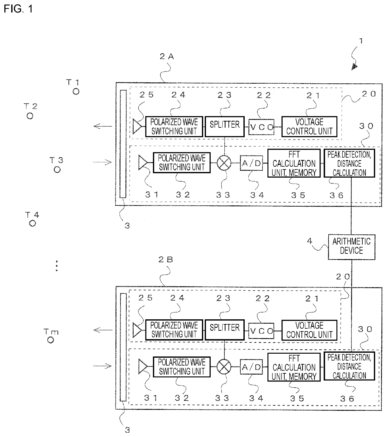
[0017]FIG. 1 is a block configuration diagram of an object position detection system 1 according to one embodiment of the present disclosure.
[0018]The object position detection system 1 is constituted by a plurality of radar devices 2A and 2B, and an arithmetic device 4. A plurality of targets T1, T2, T3, T4, . . ., and Tm serve as detection target objects.
[0019]Each of the radar devices 2A and 2B is an FMCW (Frequency Modulated Continuous Wave) radar constituted by a transmission unit 20 and a reception unit 30 and has the same configuration. The transmission unit 20 includes a voltage control unit 21, a VCO (Voltage-controlled oscillator) 22, a splitter 23, a polarized wave switching unit 24, and a horizontally and vertically polarized waves transmission antenna 25. When a voltage applied to the VCO 22 is controlled by the voltage control unit 21, th...
PUM
 Abstract
Description
Claims
Application Information
 - R&D
- Intellectual Property
- Life Sciences
- Materials
- Tech Scout
- Unparalleled Data Quality
- Higher Quality Content
- 60% Fewer Hallucinations
Browse by: Latest US Patents, China's latest patents, Technical Efficacy Thesaurus, Application Domain, Technology Topic, Popular Technical Reports.
© 2025 PatSnap. All rights reserved.Legal|Privacy policy|Modern Slavery Act Transparency Statement|Sitemap|About US| Contact US: help@patsnap.com


