Heat dissipation module and electronic device

a technology of heat dissipation module and electronic device, which is applied in the safety devices of heat exchange apparatus, indirect heat exchangers, lighting and heating apparatus, etc. it can solve the problems of liquid being unable to boil, central processing unit producing a great deal of heat, and liquid being unable to unleash the maximum efficacy, etc., and achieves better heat dissipation effect.

a technology of heat dissipation module and electronic device, which is applied in the safety devices of heat exchange apparatus, indirect heat exchangers, lighting and heating apparatus, etc. it can solve the problems of liquid being unable to boil, central processing unit producing a great deal of heat, and liquid being unable to unleash the maximum efficacy, etc., and achieves better heat dissipation effect.

US20210057306A1Active Publication Date: 2021-02-25WISTRON CORP

Image

  • Heat dissipation module and electronic device
  • Heat dissipation module and electronic device
  • Heat dissipation module and electronic device

Examples


Embodiment Construction

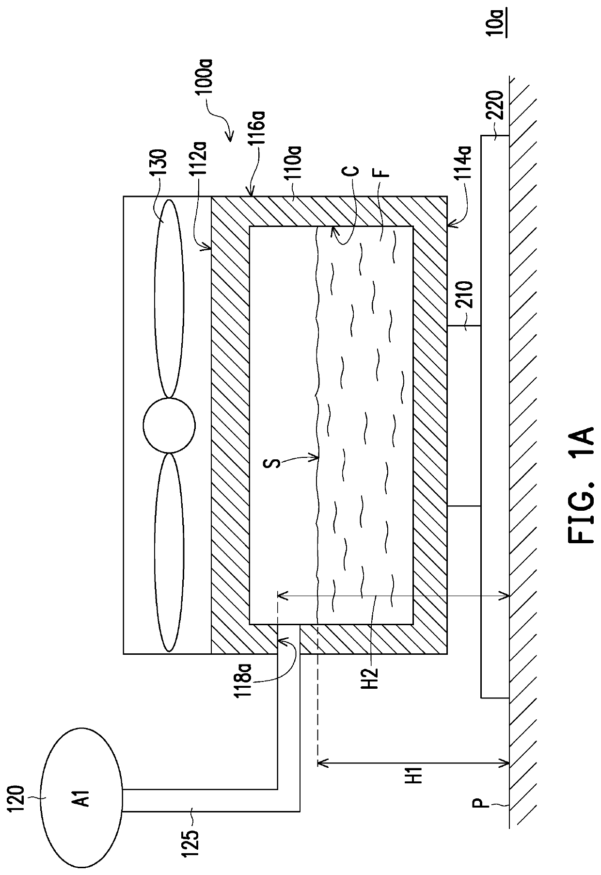
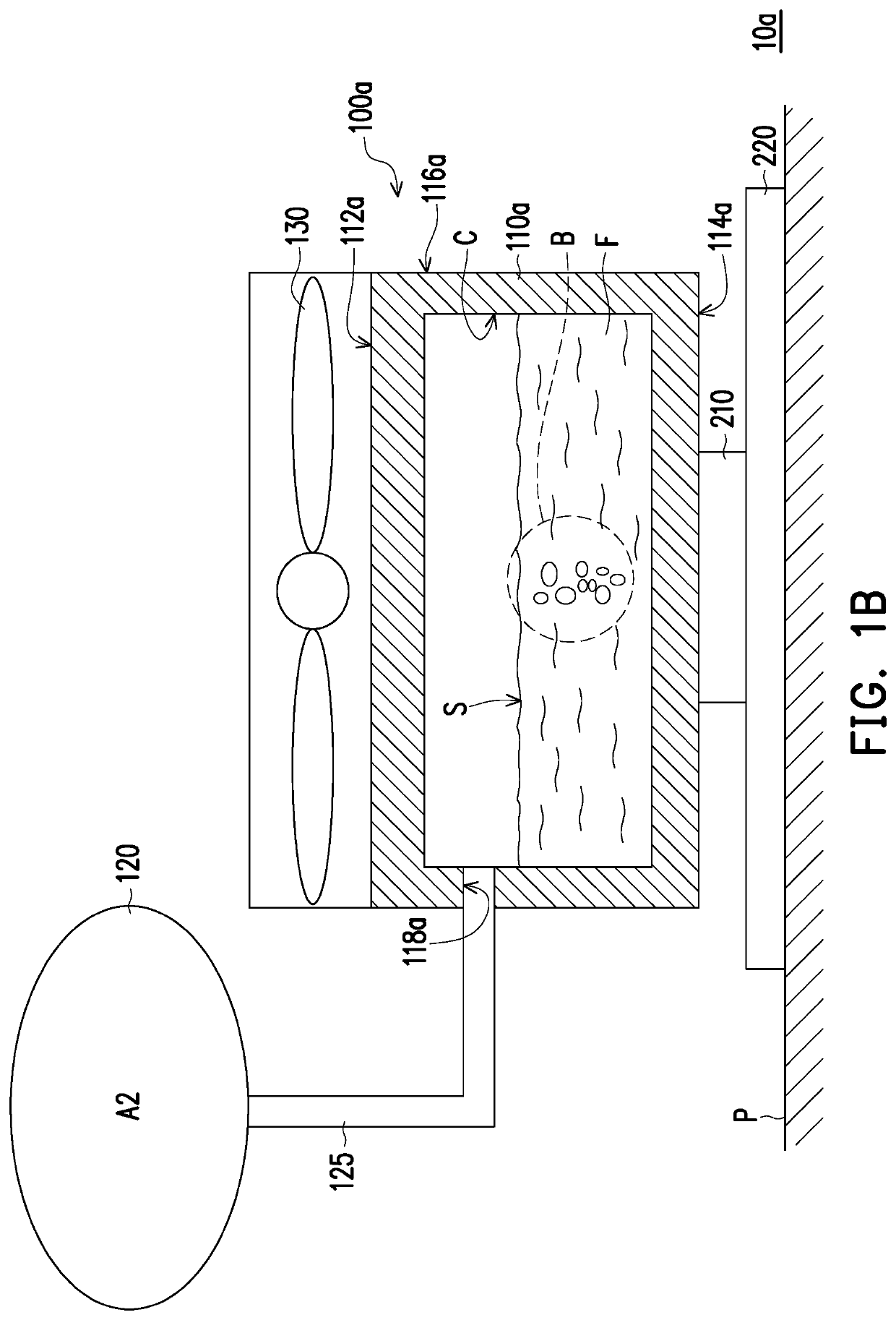
[0017]FIG. 1A is a schematic diagram of an electronic device according to an embodiment of the present invention. FIG. 1B is a schematic diagram of a buffer member expanding when a working fluid of a heat dissipation module in FIG. 1A is heated. Refer to both FIG. 1A and FIG. 1B, in the present embodiment, an electronic device 10a includes a heat dissipation module 100a, at least one heating component (only one heating component 210 is schematically depicted), and a mainboard 220. The heating component 210 is arranged on the mainboard 220 and the heat dissipation module 100a is arranged on the mainboard 220 and is in contact with the heating component 210. In addition, the heating component 210, for example, is a central processing unit or a graphic processing unit, but is not limited thereto.

[0018]Specifically, the heat dissipation module 100a of the present embodiment includes a heat dissipation portion 110a, a working fluid F, and a buffer member 120. The heat dissipation portion...


PUM

PropertyMeasurementUnit
boiling pointaaaaaaaaaa

Abstract

A heat dissipation module including a heat dissipation portion, a working fluid, and a buffer member is provided. The heat dissipation portion has a containing portion, the working fluid is contained in the containing portion, and the buffer member is connected to the containing portion. When the working fluid is heated, the buffer member is expanded to maintain a constant pressure within the containing portion.

Description

CROSS-REFERENCE TO RELATED APPLICATION[0001]This application claims the priority benefit of Taiwan application serial no. 108211231, filed on Aug. 23, 2019. The entirety of the above-mentioned patent application is hereby incorporated by reference herein and made a part of this specification.BACKGROUNDTechnical Field[0002]The present invention relates to a heat dissipation module and an electronic device, and in particular to a heat dissipation module with a buffer member and an electronic device adopting the heat dissipation module.Description of Related Art[0003]At present, the performance of central processing units (CPU) and graphic processing units (GPU) is more and more emphasized, and among them, Intel central processing units (Intel CPU) can be divided into two different types of turbos, i.e. a steady-state (PL1) turbo and a transient (PL2) turbo. In the process of the turbo, the efficiency of the central processing unit will be greatly increased, as a result, the central pr...

Claims


Application Information

Patent Timeline
25 Feb 2021
Publication
US20210057306A1
IPC
H01L23/473; H01L23/467; F28F13/02
CPC
H01L23/473; F28F2245/02; F28F13/02; H01L23/467; H01L23/427; F28F13/182; F28D15/0233; F28D2021/0029
Inventors
WU, HUAN-CHUN