Electrical Connector And Bonding System

a technology of electrical connectors and connectors, applied in the direction of connection end caps, connection contact material, coupling device connections, etc., can solve the problems of lug-to-wire interface, electrical connection jeopardization, and high risk of arcing

Active Publication Date: 2021-02-25
CARLISLE INTERCONNECT TECH
View PDF9 Cites 0 Cited by
  • Summary
  • Abstract
  • Description
  • Claims
  • Application Information

AI Technical Summary

Benefits of technology

[0007]An electrical connection system includes a mounting stud having a base configured for mounting to a conductive surface, such as a grounding surface. One or more ring-shaped lugs are configured for being positioned on the mounting stud for surrounding the mounting stud. The ring-shaped lugs are formed of an electrically conductive material and include an interior channel extending around the inside diameter thereof. A contact spring is seated within the interior channel and is electrically conductive and dimensioned to extend radially inwardly from the channel. The contact spring contacts the mounting stud when the ring-shaped lug is pos

Problems solved by technology

Furthermore, such structures are subject to motion and vibration stresses that can jeopardize the electrical connection.
As a result, there is also a risk of arcing.
The lug-to-wire interface is often subject to corrosion due to moisture.
This may lead to premat

Method used


Image

  • Electrical Connector And Bonding System
  • Electrical Connector And Bonding System
  • Electrical Connector And Bonding System

Examples


Embodiment Construction

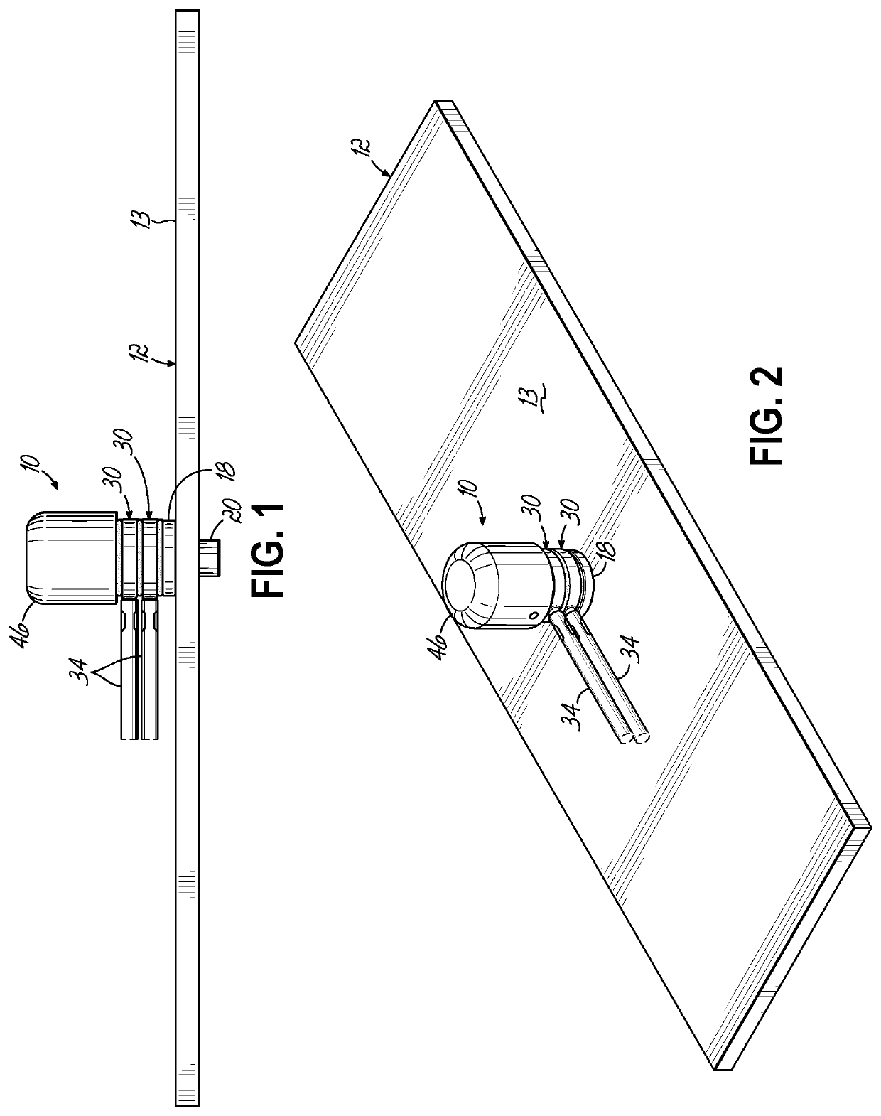
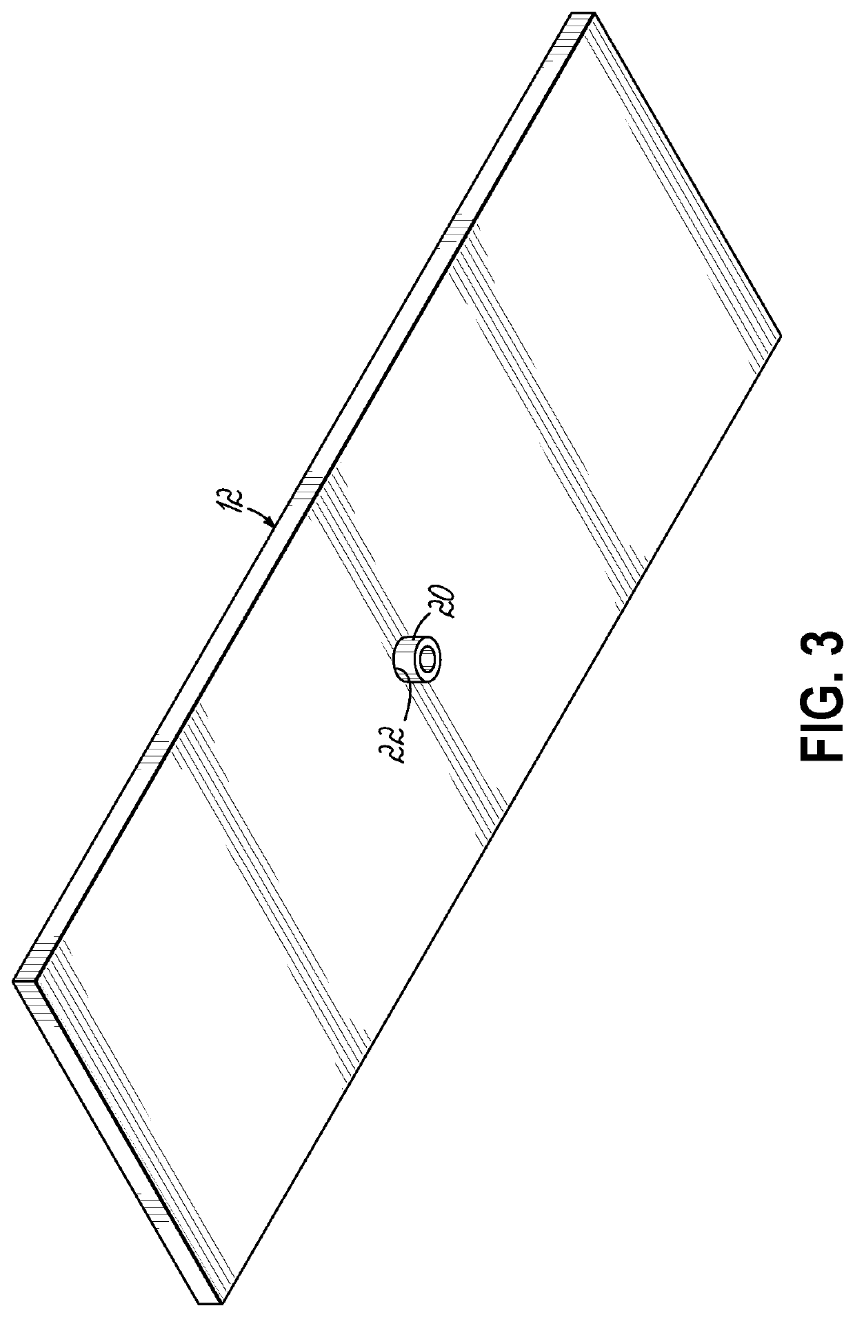
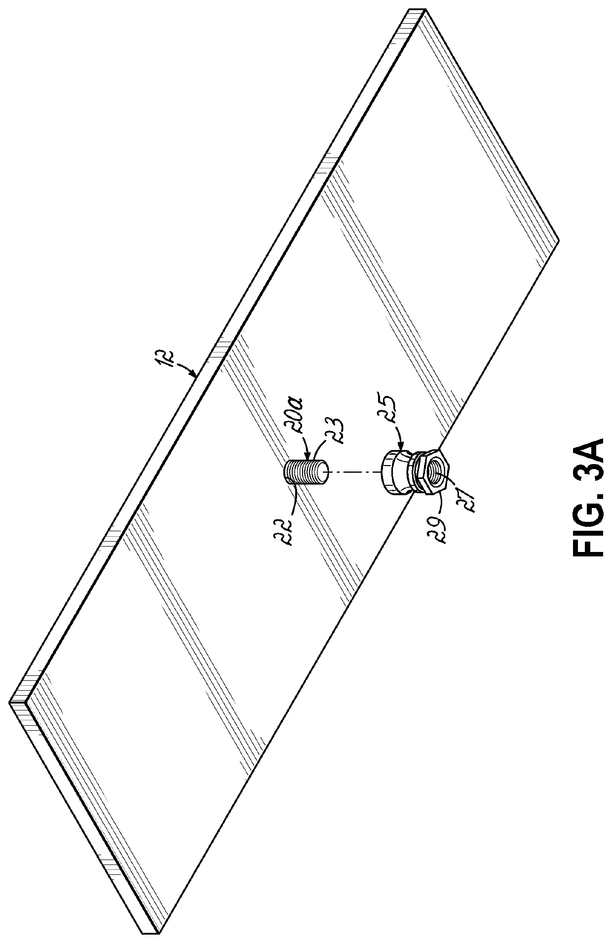
[0025]FIG. 1 illustrates a front view of an electrical connection system 10 in accordance with the invention. The electrical connection system 10 couples with a structure 12, such as a portion of an aircraft frame, for example. Generally, the structure 12 will be a conductive metal structure that is capable of providing a ground reference for the electrical connection system 10. To that end, the electrical connection system 10 may incorporate a mounting stud 14 (as illustrated in FIGS. 4, 6, 8) that includes an elongated stud body 16 that couples with a base 18. The mounting stud also includes an extension portion 20 as illustrated in FIGS. 1 and 3 for example. The mounting stud 14 engages with structure 12 or another structural surface by inserting the extension portion 20 through an appropriate opening 22 such that the base 18 is flush with the surface 13 as illustrated in FIG. 1. Extension portion 20 may be press fit or friction fit within the opening 22 or might engage in some o...


PUM


Abstract

An electrical connection system includes a mounting stud having a base configured for mounting to a conductive surface. One or more one ring-shaped lugs, formed of an electrically conductive material, are configured for being positioned on the mounting stud for surrounding the mounting stud. The ring-shaped lug includes one or a plurality of interior channels extending around the inside diameter thereof. A contact spring is seated within a respective interior channel and is electrically conductive and dimensioned to extend radially inwardly from the channel and contact the mounting stud when the ring-shaped lug is positioned thereon. The contact spring is configured to at least partially collapse in the radial direction and to provide a spring bias against the mounting stud for providing an electrical connection between the ring-shaped lug and mounting stud. A locking cap is positioned on the mounting stud over the at least one ring-shaped lug for locking with the mounting stud and securing the ring-shaped lugs on the mounting stud for a secure electrical connection.

Description

CROSS-REFERENCE TO RELATED APPLICATIONS[0001]This application claims the benefit of priority to U.S. Provisional Patent Application No. 62 / 888,767 filed Aug. 19, 2019 (pending), the disclosure of which is incorporated by reference herein.TECHNICAL FIELD OF THE INVENTION[0002]The present invention is directed to devices for connecting and securing a conductor or wire to a support structure, and particularly, but not exclusively, to an electrical attachment system for connecting conductive wires to a grounded support surface or other electrical reference surface in the construction of an aircraft.BACKGROUND OF THE INVENTION[0003]During the construction of many different structures, machines, vehicles, aircraft, etc. it is necessary to provide suitable grounding or ground signal references for the electronics and electrical systems of the structures. It is particularly critical for having proper grounding in aircraft construction, because aircraft, in addition to requiring a robust gro...

Claims


Application Information

Patent Timeline
IPC IPC(8): H01R4/66H01R4/30H01R4/36H01R11/12H01R13/52
CPCH01R4/66H01R4/307H01R13/5219H01R11/12H01R4/366H01R4/22H01R4/302H01R4/304H01R4/54H01R4/646H01R4/70H01R13/187H01R13/521
Inventor KOLARICH, ROBERTA A.KRAMER, MICHAEL I.MYLES, ANDREA M.
Owner CARLISLE INTERCONNECT TECH
Why Eureka
Try Eureka