Split cylinder resonator and method of calculating permittivity

a technology of resonators and cylinders, applied in waveguides, waveguide type devices, instruments, etc., can solve problems such as inability to accurately measure resonance characteristics

Inactive Publication Date: 2021-03-04
EM LABS INC
View PDF0 Cites 0 Cited by
  • Summary
  • Abstract
  • Description
  • Claims
  • Application Information

AI Technical Summary

Benefits of technology

The present invention aims to provide a split cylinder resonator that can accurately measure the complex permittivity of a dielectric sheet used in 5G communication and automotive radar without being affected by the TM111 mode. The resonator has a protruded portion on its cavity that raises the resonance frequency of the TM111 mode above that of the TE011 mode. This prevents the TM111 mode from interfering with the measurement of complex permittivity, even when a sample of the dielectric material is inserted.

Problems solved by technology

Thus, the resonance frequencies of the TM111 mode and the TE011 mode are close to each other (overlapped in some cases) and the resonance characteristics may not be measured correctly.

Method used


Image

  • Split cylinder resonator and method of calculating permittivity
  • Split cylinder resonator and method of calculating permittivity
  • Split cylinder resonator and method of calculating permittivity

Examples


embodiments

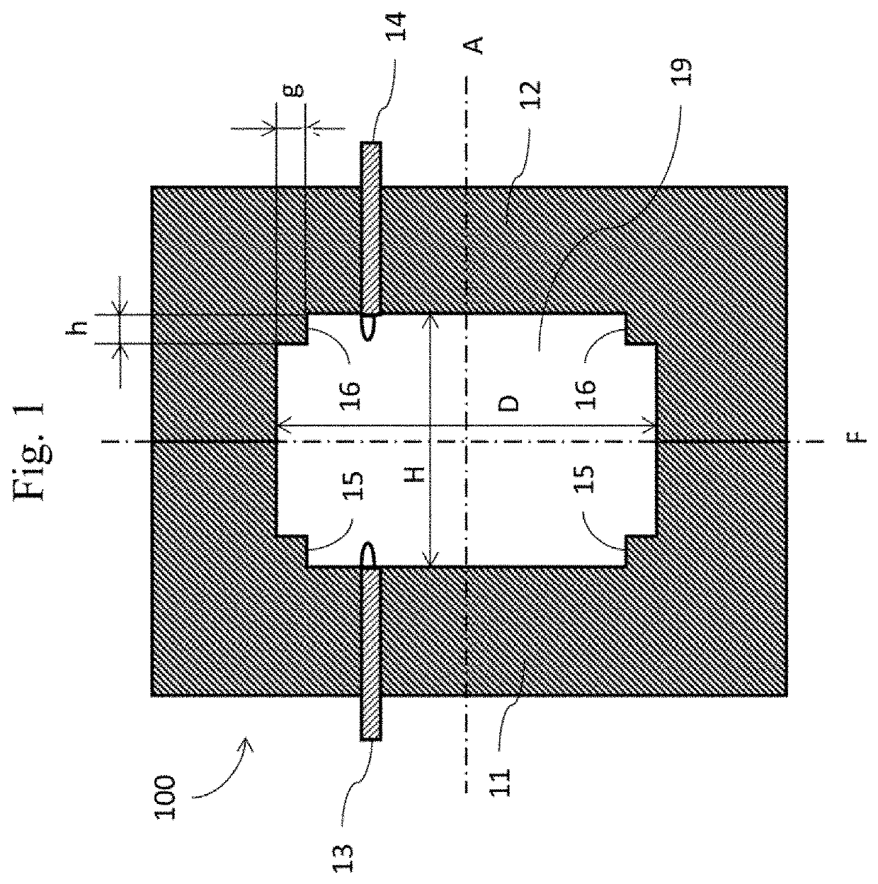
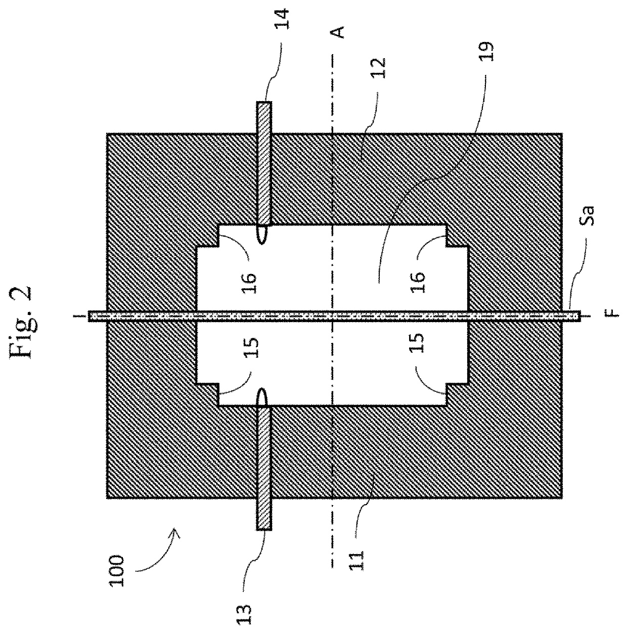
[0045]FIG. 1 is a schematic diagram showing a cross-section of a split cylinder resonator (without measurement sample). FIG. 2 is a schematic diagram showing a cross-section of the split cylinder resonator in which the measurement sample is inserted. A split cylinder resonator 100 has two conductive bodies 11, 12 and two coaxial cables 13, 14. The two conductive bodies 11, 12 have the bottomed cavities which have the substantially same shape with each other. The split cylinder resonator 100 is formed by combining the conductive bodies 11, 12 so that the bottomed cavities face with each other. The bottomed cavities are formed in a cylindrical (circular columnar) shape having the side surface and the bottom surface so that opening portion is located opposite to the bottom surface. A cavity 19 (integrated cavity) having a cylindrical shape is formed by combining the bottomed cavity of the conductive body 11 and the bottomed cavity of the conductive body 12. Protruded portions 15, 16 ar...


PUM


Abstract

A split cylinder resonator has: a first conductive body having a first cavity formed in a cylindrical shape having the side surface and the bottom surface; a second conductive body having a second cavity formed in a cylindrical shape having the side surface and the bottom surface and arranged so that the second cavity faces the first cavity; first and second coaxial cables respectively having first and second loop antennas at a tip, the first and second loop antennas being exposed to an integrated cavity which is formed by the first cavity and the second cavity, the first and second coaxial cables facing each other. Each of the first conductive body and the second conductive body has a protruded portion protruded from a part of at least one of the side surface and the bottom surface of the first conductive body and the second conductive body toward the integrated cavity.

Description

CROSS-REFERENCES TO RELATED APPLICATIONS[0001]This patent specification is based on Japanese patent application, No. 2019-161539 filed on Sep. 4, 2019 in the Japan Patent Office, the entire contents of which are incorporated by reference herein.BACKGROUND OF THE INVENTION1. Field of the Invention[0002]The present invention relates to a split cylinder resonator which is a measurement device of complex permittivity (complex dielectric constant) of dielectric material and related to a method of calculating the complex permittivity using the device. Especially, the present invention relates to the measurement device suitable for measuring the complex permittivity of the dielectric material in a microwave and millimeter wave bands.2. Description of the Related Art[0003]For measuring the complex permittivity of the dielectric material in the microwave band, Cavity resonator perturbation method, Transmission line method, Fabry-Perot resonator method, Balanced-type circular disk resonator m...

Claims


Application Information

Patent Timeline
IPC IPC(8): G01N27/02H01P7/06H01P3/06H01Q7/00
CPCG01N27/02H01Q7/00H01P3/06H01P7/06G01N22/00
Inventor YANAGIMOTO, YOSHIYUKI
Owner EM LABS INC
Why Eureka
Try Eureka