Security elements and method of manufacture thereof

a technology of security elements and manufacturing methods, applied in the field of security elements, can solve the problems of noise of security elements, misregistration between different colours, etc., and achieve the effects of reducing thickness, reducing thickness, and reducing thickness

Pending Publication Date: 2021-03-11
DE LA RUE INT LTD
View PDF6 Cites 3 Cited by
  • Summary
  • Abstract
  • Description
  • Claims
  • Application Information

AI Technical Summary

Benefits of technology

[0026]Where convex sub-regions are used, whether they be as part of one or two-dimensional arrays of image regions, the thickness of the security element may be minimised by using a surface shaped to define a diverging Fresnel mirror. A diverging Fresnel mirror is essentially an arrangement of facets that substantially replicate the surface of a convex mirror, but eliminate the unnecessary thickness towards the centre of the mirror arrangement by providing each facet at substantially the same height. This structure operates on the same principle as Fresnel lenses, which are well known in the art. These structures have the advantage of reduced thickness compared with the convex structure they emulate. The facets of a so-called diverging Fresnel mirror are preferably convex to more accurately replicate a convex structure, but could also be substantially planar to approximate respective areas of the replicated convex structure.
[0027]Convex sub-regions may be particularly preferably employed where the sub-regions exhibit image effects such as animations, image switches, or apparent rotation of an object, as described above. In particular, convex sub-regions may present a more continuous appearance of the effect across a range of viewing angles corresponding to the convex direction of the sub-regions.
[0028]The plasmonic nanostructures of the first, second and/or third arrays of plasmonic nanostructures may be discontinuously pro...

Problems solved by technology

In contrast, processes that use printed inks in generating an optically variable effect, e.g. security elements that use printed image elements in combination with focussing elements, often suffer from misregistration between different colours since they are typically printed in separate print processe...

Method used


Image

  • Security elements and method of manufacture thereof
  • Security elements and method of manufacture thereof
  • Security elements and method of manufacture thereof

Examples


Embodiment Construction

[0065]A security element according to a first embodiment will now be described with reference to FIGS. 1 to 6B.

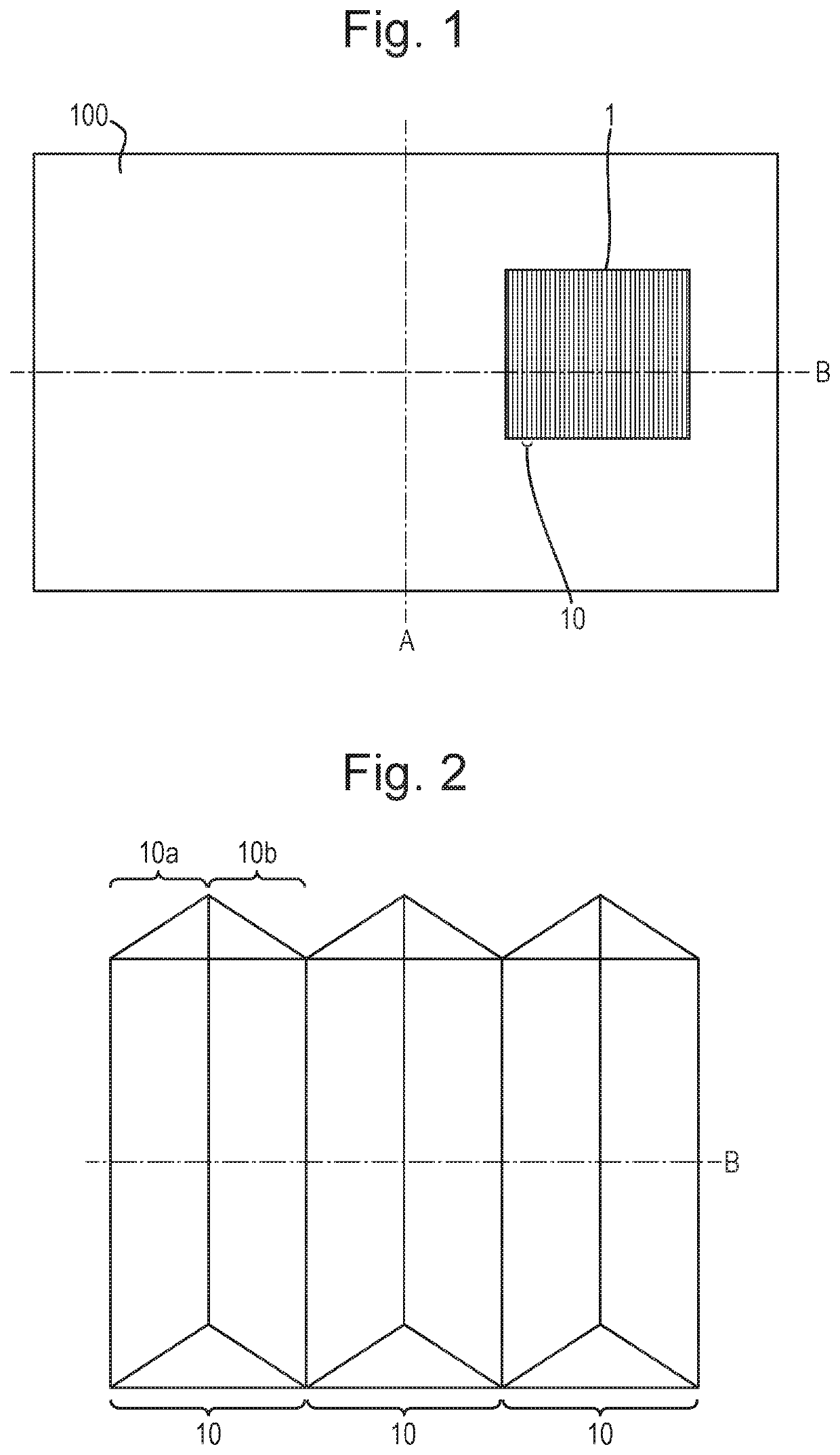
[0066]FIG. 1 shows a security document 100, in this case a banknote, with a security element 1. The security document has a short axis A and a long axis B perpendicular to the short axis. The security element has a first surface that faces away from the security document. This first surface is made up of an array of image regions 10, in this case elongate image regions, each elongate image region extending in a first direction, i.e. along the direction of the axis A. The array of elongate image regions are arranged so as to repeat along a second direction along the surface, i.e. along the direction of axis B, the image regions repeating so as to provide the width of the security element.

[0067]FIG. 2 shows a small area of the security element, illustrating the arrangement of the surface of the security element across three image regions 10 in a perspective view. As can be se...


PUM


Abstract

A security element including: a first layer having a first surface; an array of image regions across the surface, each including at least first and second sub-regions; a first array of plasmonic nanostructures in or on the surface across the first sub-regions, defining in each a corresponding portion of a first image; a second array across the second sub-regions, defining in each a corresponding portion of a second image; wherein each sub-region has a respective average inclination and the average inclinations of the first sub-regions are such that the first image is displayed at least at a first viewing angle and those of the second sub-regions are such that the second image is displayed at least at a second viewing angle different from the first and the second image is substantially not or only partially displayed at least at the first angle. Also, a method of manufacturing the security element.

Description

FIELD OF THE INVENTION[0001]The present invention relates to security elements such as those suitable for use in or on security documents such as banknotes, identity documents, passports, certificates and the like, as well as methods for manufacturing such security elements.DESCRIPTION OF THE RELATED ART[0002]To prevent counterfeiting and enable authenticity to be checked, security documents are typically provided with one or more security elements which are difficult or impossible to replicate accurately with commonly available means, particularly photocopiers, scanners or commercial printers.[0003]Many conventional security elements utilise optically variable effects, i.e. an appearance that changes upon rotation of the device, which cannot be replicated by copying, as with a photocopier or scanner. One class of optically variable security elements includes those that utilise diffractive optically variable effect generating relief structures, such as diffraction gratings, to gener...

Claims


Application Information

Patent Timeline
IPC IPC(8): B42D25/29B42D25/324
CPCB42D25/29B82Y20/00B42D25/324
Inventor HOLMES, BRIAN
Owner DE LA RUE INT LTD
Why Eureka
Try Eureka