
Arrangement having plural temperature-control stations for heat treating component parts, and their handling

a technology of temperature control station and heat treatment component, which is applied in the direction of muffle furnace, furnace, charge manipulation, etc., can solve the problems of reducing the effectiveness of hood-type furnaces, high degree of accuracy, and high time-consuming and labor-intensive problems of placing furnace hoods

Active Publication Date: 2021-03-11
EBNER-INDUSTRIEOFENBAU GMBH
View PDF0 Cites 1 Cited by
  • Summary
  • Abstract
  • Description
  • Claims
  • Application Information

AI Technical Summary

Benefits of technology

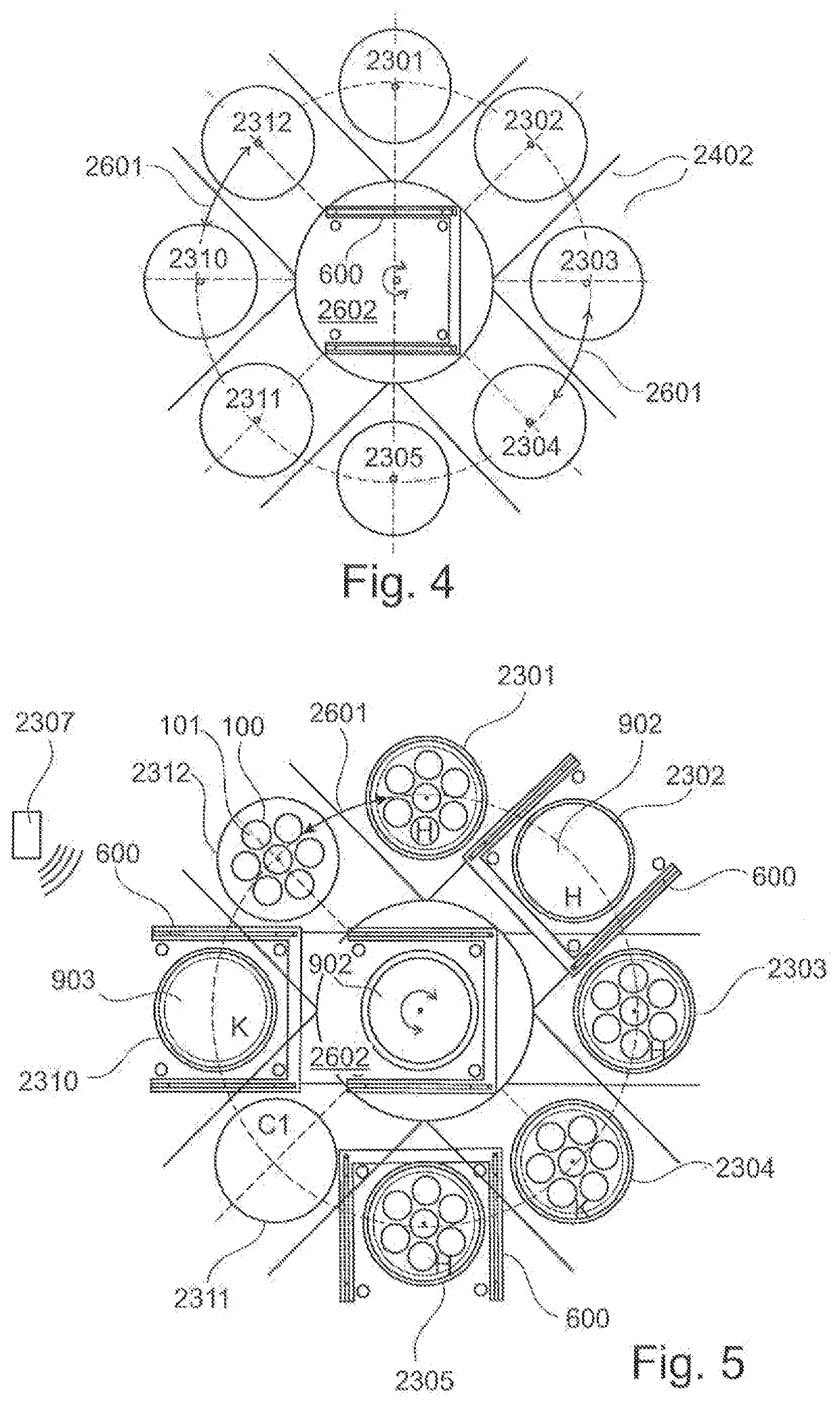
The patent describes a handling system for handling and charging component parts, such as wire coils, in a heat treatment process. The system includes a circular apposition of stations that allows the handling system to reach each station quickly without having to perform long translatory movements. The system also includes a ring or ring segment arrangement that allows for short transfer paths and short charging times. The system can be used to supply or remove multiple component parts simultaneously, replacing a crane. The system includes a base frame and gripper frame that can be moved out of the center in a translatory motion to place or remove the functional devices. The system also includes a heat treatment device that can be used to control the temperature of the component parts during the heat treatment process. The handling system functions as a rail-guided lift truck that can de-charge the annealing base, load the furnace with a new charge, and handle the hood handling. The system includes different attachments and set-on devices for carrying out the individual work steps.

Problems solved by technology

This requires a high degree of accuracy and results in that the placing of the furnace hoods needs a high expenditure of time.
Such a long set-up time reduces the effectiveness of the hood-type furnace.
During the placing of the individual crown supports, the hood-type furnace cannot be operated, so that a long set-up time is required.

Method used


Image

  • Arrangement having plural temperature-control stations for heat treating component parts, and their handling
  • Arrangement having plural temperature-control stations for heat treating component parts, and their handling
  • Arrangement having plural temperature-control stations for heat treating component parts, and their handling

Examples


Embodiment Construction

[0080]Same or similar components in different figures are provided with the same reference numerals. The representations in the figures are schematic.

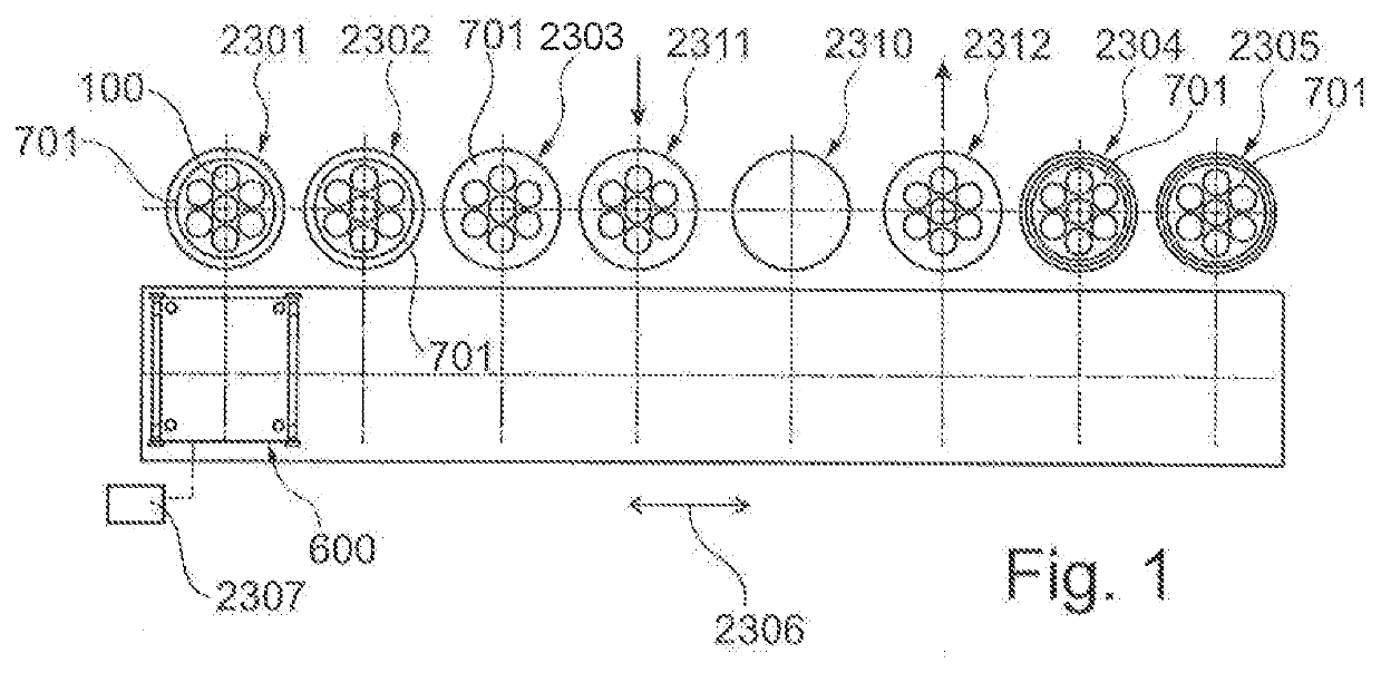
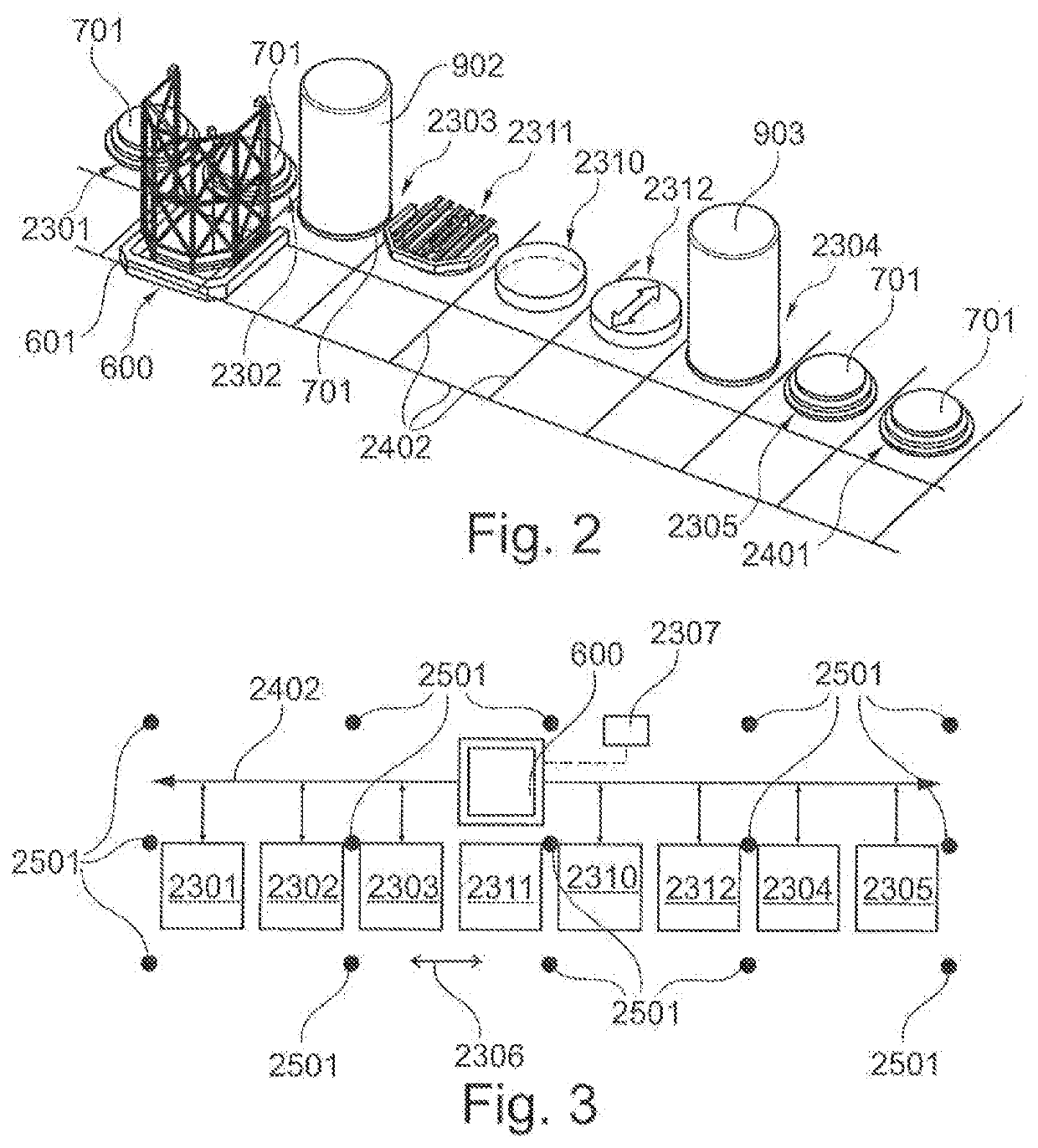
[0081]FIG. 1 to FIG. 3 show schematic representations of an arrangement having a linear apposition 2306 of temperature control stations 2301, 2302, 2303, 2304, 2305 for heat treating component parts, charging stations 2311, 2312 and a storage location 2310 according to an exemplary embodiment of the present invention. In FIG. 2, a sixth temperature control station 2401 is additionally shown.

[0082]The temperature control stations 2301, 2302, 2303, 2304, 2305 each may have a temperature control device 701, in each of which a functional device may be placeable. The functional device may for example be a charging device 100 for carrying component parts 101 to be temperature-controlled, in particular a charging device as shown in FIG. 8, a guide cylinder 801 or a furnace hood 902, 903. Furthermore, the arrangement may have two charging stat...


PUM

PropertyMeasurementUnit
diameteraaaaaaaaaa
diameteraaaaaaaaaa
heightaaaaaaaaaa

Abstract

The present invention relates to an arrangement for heat treating component parts. The arrangement has a first temperature control station for heat treating component parts and a second temperature control station for heat treating component parts, wherein the first temperature control station and the second temperature control station each have a temperature control device, on each of which a functional device is placeable. The functional device is a charging device for carrying component parts to be temperature-controlled or a device of the temperature control device. The arrangement further has a charging station, on which the functional device is placeable, and a handling system for handling the functional device, wherein the handling system is configured to convey the functional device between the charging station, the first temperature control station and the second temperature control station.

Description

REFERENCE TO RELATED APPLICATIONS[0001]The present application is a national phase application derived from the international patent application no. PCT / EP2019 / 052343, filed Jan. 31, 2019, which in turn claims the benefits of the filing dates of the German patent application no. DE 10 2018 103 145.9, filed Feb. 13, 2018, all of which are incorporated herein by reference in their entireties.TECHNICAL FIELD[0002]The present invention relates to an arrangement having plural temperature control stations for heat treating component parts, and a method for heat treating component parts in plural temperature control stations.BACKGROUND OF THE INVENTION[0003]In stationary industrial furnaces, such as hood-type furnaces, a base of the hood-type furnace is first loaded with a batch (or charge) of component parts to be heated. Subsequently, an appropriate furnace hood is placed over the batch so that the furnace hood together with the base forms an annealing chamber. The annealing chamber can ...

Claims


Application Information

Patent Timeline
Patent Type & Authority Applications(United States)
IPC IPC(8): F27B9/02F27B9/24
CPCF27B9/028F27B11/00F27B9/2407F27B1/20F27B1/21F27B5/12F27B5/13F27B9/02F27B9/16F27B9/20F27B9/36F27D3/0024C21D9/663C21D9/675C21D9/667
Inventor EBNER, ROBERTGRILLBERGER, GÜNTERLADNER, PETERLAUBER, MARTIN
Owner EBNER-INDUSTRIEOFENBAU GMBH
Learn More