Milling tool and workpiece machining method

a technology of workpieces and milling tools, which is applied in the direction of milling cutters, tool workpiece connection, manufacturing tools, etc., can solve the problems of reducing machining speed and machining accuracy, reducing the ability to machine peripheral surfaces with a radius of curvature greater than or equal, and achieving high quality and efficient machined effects

Pending Publication Date: 2021-03-18
MAKINO MILLING MASCH CO LTD
View PDF34 Cites 4 Cited by
  • Summary
  • Abstract
  • Description
  • Claims
  • Application Information

AI Technical Summary

Benefits of technology

[0009]According to the present invention, since the head of the milling tool has an expanding diameter section, the diameter of which gradually increases along the direction from a proximal end toward the distal end, and a decreasing diameter section, the diameter of which gradually decreases along the direction from a maximum diameter section toward the distal end, and cutting edges are provided on the expanding diameter section and the decreasing diameter section, the milling tool can diagonally approach the undercut part of the workpiece and machining of the workpiece can be performed without interference with the return flange, whereby the protruding length of the shank can be shortened. The undercut part can be machined efficiently and with high quality under high machine conditions.

Problems solved by technology

However, when the rib height becomes greater, the shank must be lengthened accordingly, and a large lateral force (bending stress) acts on the shank, causing deformation of the shank, whereby there is a problem in that machining speed and machining accuracy are reduced.
Furthermore, in the T-shaped cutter of Patent Literature 1, there is a problem in that only an inner peripheral surface having a radius of curvature greater than or equal to the radius of the head of the T-shaped cutter can be machined when the curved inner peripheral surface at the corner where the ribs of the workpiece intersect is machined.

Method used


Image

  • Milling tool and workpiece machining method
  • Milling tool and workpiece machining method
  • Milling tool and workpiece machining method

Examples


first embodiment

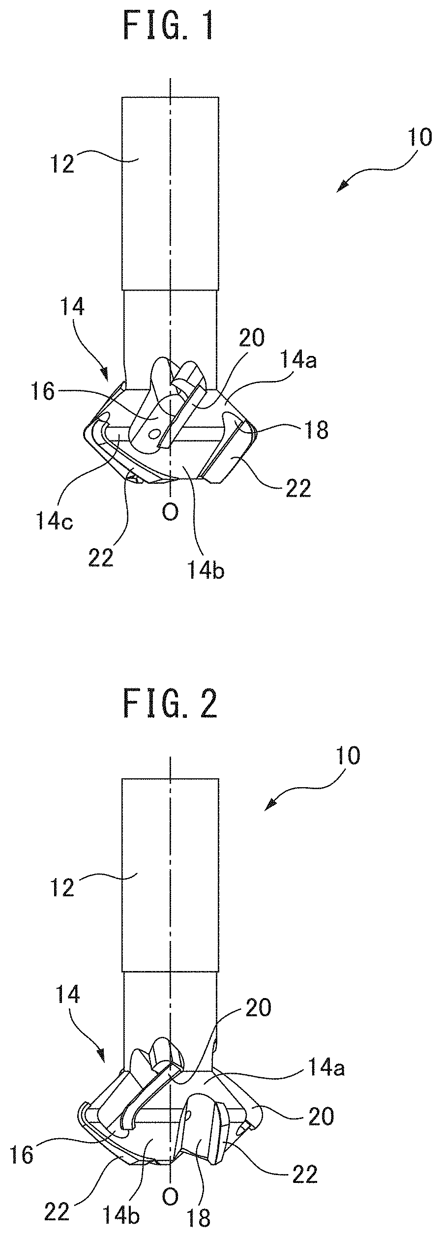
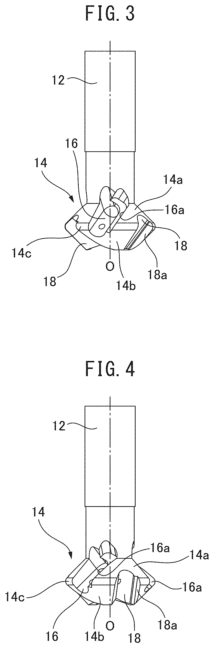
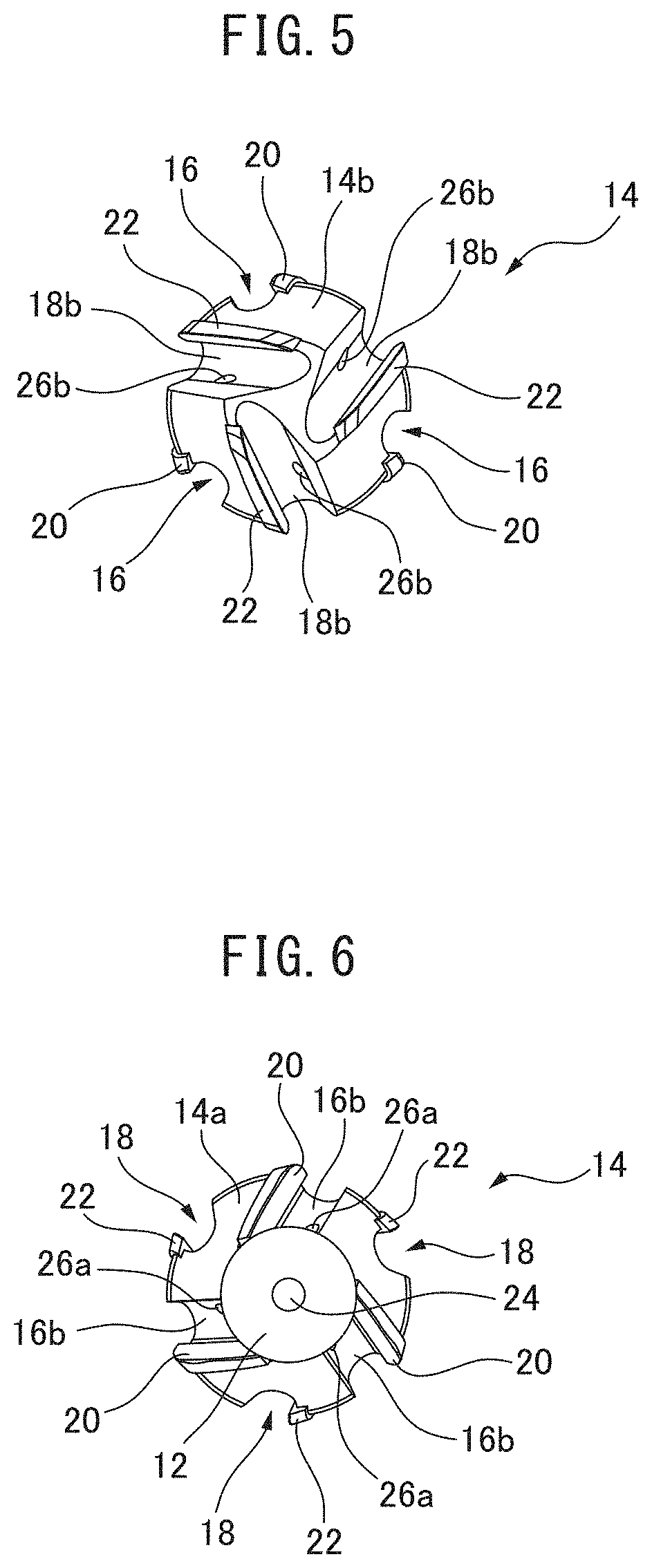
[0054]First, referring to FIGS. 1 to 12, the milling tool of the present invention will be described.

[0055]A milling tool 10 comprises a cylindrical shank 12 and a head 14 which is integrally formed with the tip of the shank 12. The head 14 has an approximately frustoconical expanding diameter section 14a, the diameter of which increases along the direction from the proximal end which contacts the shank 12 toward the distal end, and an approximately frustoconical decreasing diameter section 14b, the diameter of which decreases along the direction from the expanding diameter section 14a toward the distal end, and the head is formed into substantially a double conical shape. A transition part 14c as a maximum diameter part, at which the diameter is maximum, is formed between the expanding diameter section 14a and the decreasing diameter section 14b. The head 14 has upper grooves 16 formed in the expanding diameter section 14a and lower grooves 18 formed in the decreasing diameter sect...

second embodiment

[0077]Next, the milling tool of the present invention will be described with reference to FIGS. 30 to 40.

[0078]Though the inserts were divided into upper inserts 20 and lower inserts 22 in the first embodiment, in the second embodiment, both inserts 20, 22 are integral so as to form a single V-shaped insert, and this insert is attached from the expanding diameter section of the head to the decreasing diameter section.

[0079]A milling tool 50 comprises a cylindrical shank 52 and a head 54 which is integrally formed with the tip of the shank 52. The head 54 has an approximately frustoconical expanding diameter section 54a, the diameter of which increases from the proximal end which contacts the shank 52 in the direction toward the proximal end, and an approximately frustoconical decreasing diameter section 54b, the diameter of which decreases along the direction from the expanding diameter section 54a toward the distal end, and the head 54 has substantially a double conical shape. A tr...


PUM


Abstract

A milling tool is configured from a shank part and a head with a cutting edge that is provided on the leading end of the shank part. The head comprises an expanding diameter section, the diameter of which expands gradually from the base end that contacts the shank part in the direction of the leading end, and a decreasing diameter section, the diameter of which gradually decreases from the maximum diameter section in the direction of the leading end. At least one cutting edge is provided on each of the expanding diameter section and the decreasing diameter section.

Description

CROSS-REFERENCE TO RELATED APPLICATIONS[0001]This application is a U.S. national stage application under 35 USC 371 of International Patent Application No. PCT / JP2017 / 044791, filed Dec. 13, 2017, the entire contents of which are incorporated herein by reference.FIELD OF THE DISCLOSURE[0002]The present invention relates to a milling tool and workpiece machining method which are capable of machining an undercut part such as a rib having a return flange with high efficiency and high accuracy.BACKGROUND OF THE DISCLOSURE[0003]Patent Literature 1 describes a T-shaped cutter for forming an undercut in a side surface of a workpiece. The T-shaped cutter has a head which is connected to one end of a shank, wherein a plurality of bottom blades having cutting edges on a distal end side of the head and a plurality of upper blades having cutting edges on a base edge side are alternately arranged in the peripheral direction, and the cutting edges of the bottom blades and the upper blades are inte...

Claims


Application Information

Patent Timeline
Patent Type & Authority Applications(United States)
IPC IPC(8): B23C3/13B23C5/10
CPCB23C3/13B23C5/10B23C3/00B23C5/1081B23C5/18B23C2265/08B23C2250/12B23C2240/08B23C2220/56B23C2220/04B23C5/28
Inventor UENO, HIROSHIMIYAMOTO, RYOICHINAGATA, FUKUHITO
Owner MAKINO MILLING MASCH CO LTD
Why Eureka
Try Eureka