Cutting machine and method

a cutting machine and cutting technology, applied in the direction of printing, laser beam welding apparatus, auxiliary devices for welding, etc., can solve the problems of slow operation speed, limited cutting speed of the machine, difficult to move quickly, etc., and achieve the effect of accurately retaining the position of the material and loss of cutting accuracy

a cutting machine and cutting technology, applied in the direction of printing, laser beam welding apparatus, auxiliary devices for welding, etc., can solve the problems of slow operation speed, limited cutting speed of the machine, difficult to move quickly, etc., and achieve the effect of accurately retaining the position of the material and loss of cutting accuracy

US20210086296A1Inactive Publication Date: 2021-03-25BLACKMAN & WHITE CUTTING SOLUTIONS LTD

Image

  • Cutting machine and method
  • Cutting machine and method
  • Cutting machine and method

Examples


first embodiment

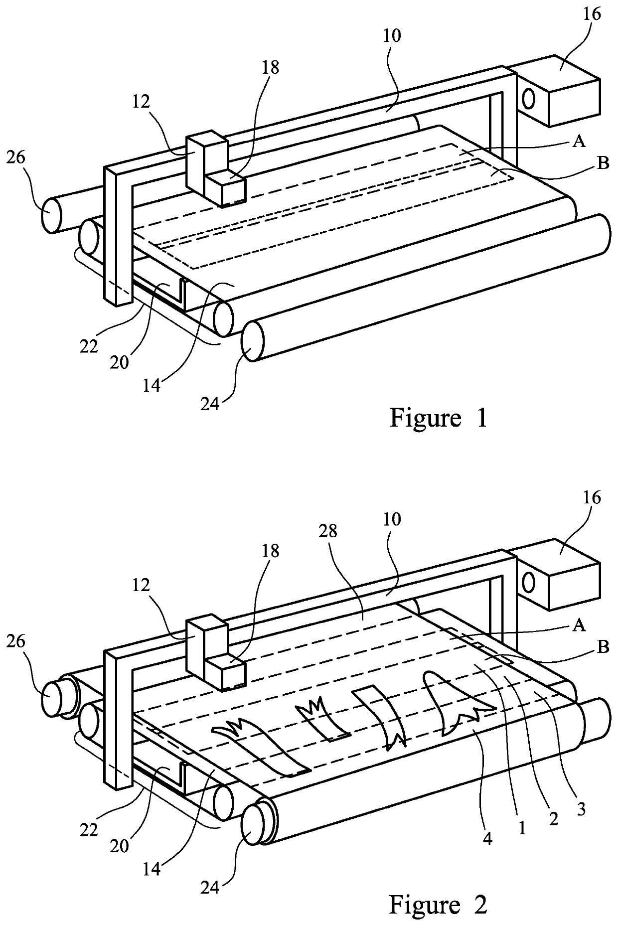
[0047]FIG. 1 is a perspective view of a laser cutting machine according to the invention;

[0048]FIG. 2 is a perspective view of the laser cutting machine of FIG. 1 illustrating the movement of a sheet of material through the laser cutting machine;

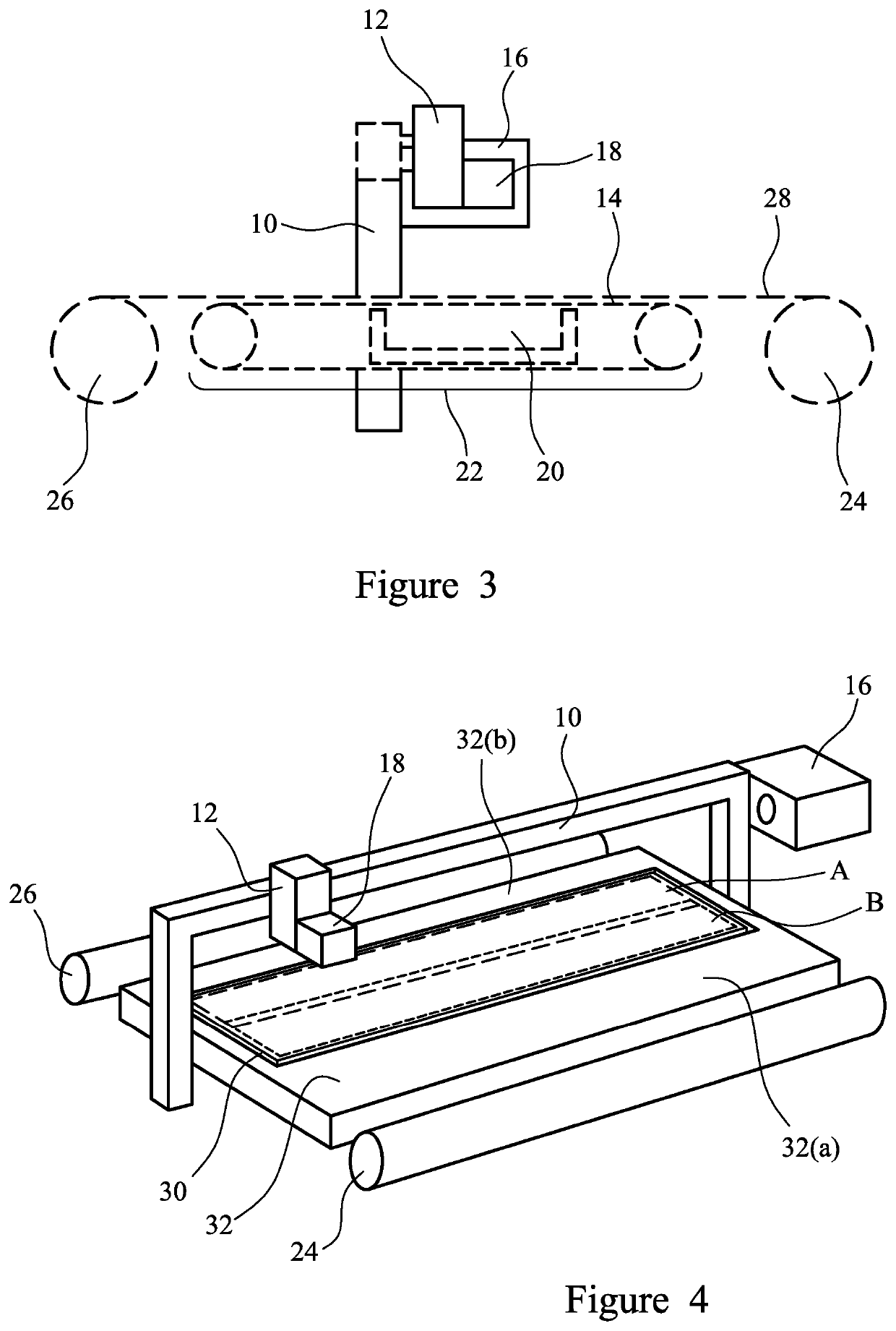
[0049]FIG. 3 is a cross section of the laser cutting machine according to the first embodiment of the invention;

second embodiment

[0050]FIG. 4 is a perspective view of a laser cutting machine according to the invention;

third embodiment

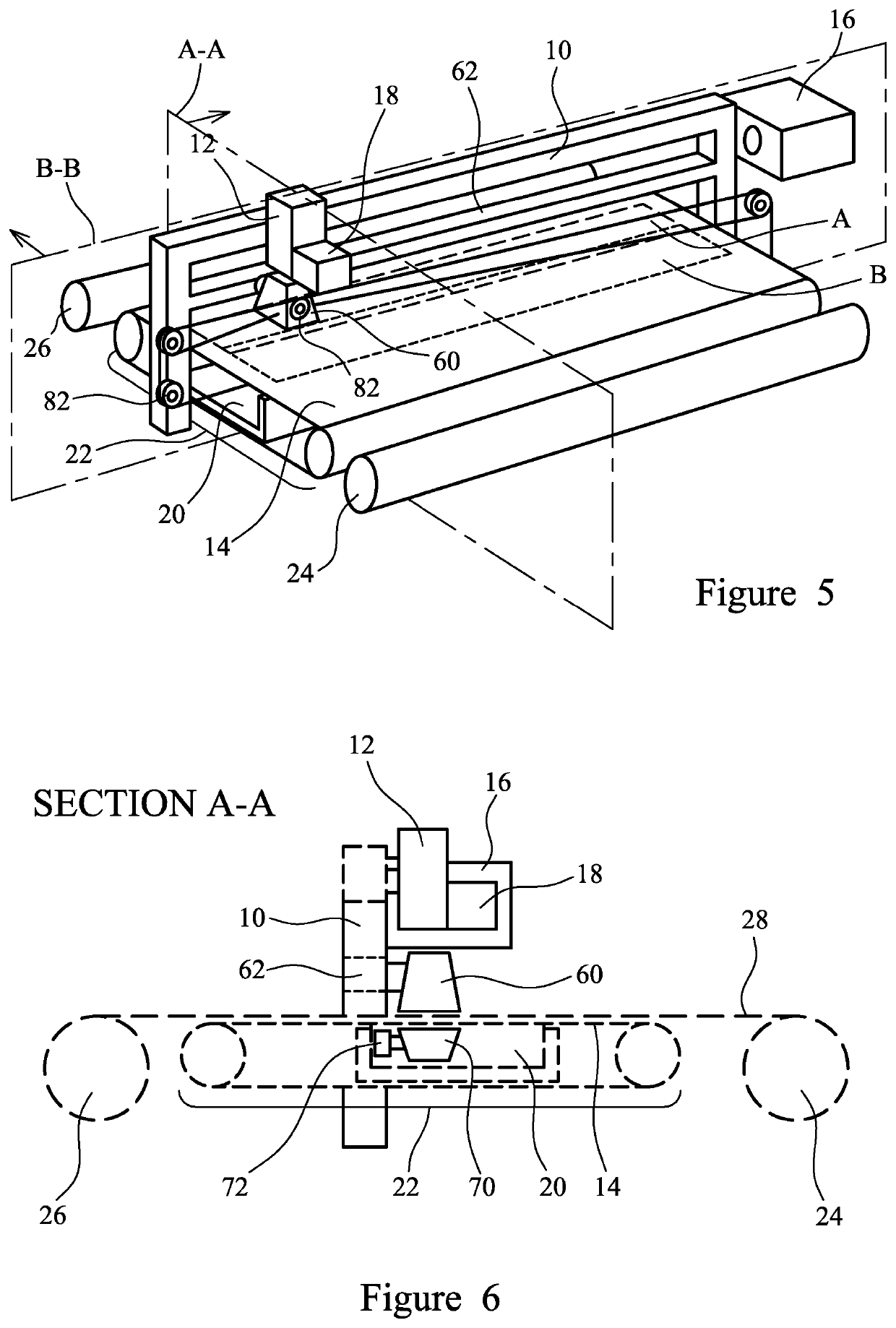
[0051]FIG. 5 is a perspective view of a laser cutting machine according to the invention;

[0052]FIG. 6 is a longitudinal section of the laser cutting machine of FIG. 5, on A-A;

[0053]FIG. 7 is a more detailed longitudinal section of the laser cutting machine of FIG. 5, on A-A;

[0054]FIG. 8 is a lateral section showing part of the laser cutting machine of FIG. 5, on B-B, namely the purge and vacuum system in the scanning area; and

[0055]FIG. 9 is a schematic diagram of a further embodiment of the invention, in which a laser cutting machine is integrated with a printing machine, or printer.

[0056]A laser cutting machine according to a first embodiment of the invention is shown in FIG. 1. It comprises a fixed support or gantry 10 on which a laser scanner 12 is traversably mounted. Beneath the gantry is a cutting surface 14 which comprises a metal mesh conveyor belt 22 for carrying a sheet of material for cutting. The traversably-mounted laser scanner is controllable to direct a laser beam f...


PUM

PropertyMeasurementUnit
operating distanceaaaaaaaaaa
cutting areaaaaaaaaaaa
areaaaaaaaaaaa

Abstract

In a laser cutting machine for cutting a sheet of material, a laser scanner (12) is traversable in a lateral direction across a cutting surface (14). The laser scanner is controllable to direct a laser beam onto the cutting surface within a cutting area (A) of the cutting surface. A material-advancing mechanism is provided that is controllable to incrementally advance the sheet of material in a longitudinal direction over the cutting surface. In use, the material-advancing mechanism is controllable to position and hold stationary successive laterally- extending portions of the material in the cutting area. The laser scanner is controllable to cut each successive laterally-extending portion of the material held stationary in the cutting area before the material is advanced.

Description

FIELD OF THE INVENTION[0001]The invention relates to a cutting machine and method. In particular, the invention relates to a cutting machine and method for cutting or embossing a sheet of material.BACKGROUND OF THE INVENTION[0002]Lasers have been used to cut out shapes in sheets or webs of many materials, for example fabrics, paper products and metals. Laser cutting machines can also be used to emboss or mark sheets of material, by reducing the intensity of the laser beam so as not to penetrate through a sheet of material. In this document, the term cutting should be taken, where appropriate, to include embossing.[0003]In a conventional laser cutting machine, a sheet of material for cutting is laid out on a cutting table. A laser is arranged to direct a laser beam downwardly onto the table to cut the sheet of material according to a desired cutting pattern. The laser is traversably mounted on a moveable gantry, which spans a width of the cutting table, and the gantry is movable in a...

Claims


Application Information

Patent Timeline
25 Mar 2021
Publication
US20210086296A1
IPC
B23K26/082; B23K26/08; B23K26/38; B23K37/02; B41J11/00; B41J15/04; B41J3/38
CPC
B23K26/082; B23K26/0838; B23K26/38; B23K2103/38; B41J11/007; B41J15/048; B41J3/38; B23K37/0235
Inventors
WHITE, ALEXANDER LESLIE