Sole Structure for a Shoe

Pending Publication Date: 2021-04-01
MIZUNO CORPORATION
View PDF3 Cites 12 Cited by
  • Summary
  • Abstract
  • Description
  • Claims
  • Application Information

AI Technical Summary

Benefits of technology

[0023]As mentioned above, according to the present invention, at the time of impacting the ground, an impact force on landing can be absorbed by an elastic deformation of the second shock absorbing component formed of a soft elastic member. At the same time, a shock absorbance can be improved and a higher resilience can be achieved by a

Problems solved by technology

Therefore, the prior-art structure did not fully consider a load tran

Method used


Image

  • Sole Structure for a Shoe
  • Sole Structure for a Shoe
  • Sole Structure for a Shoe

Examples


Example

First Embodiment

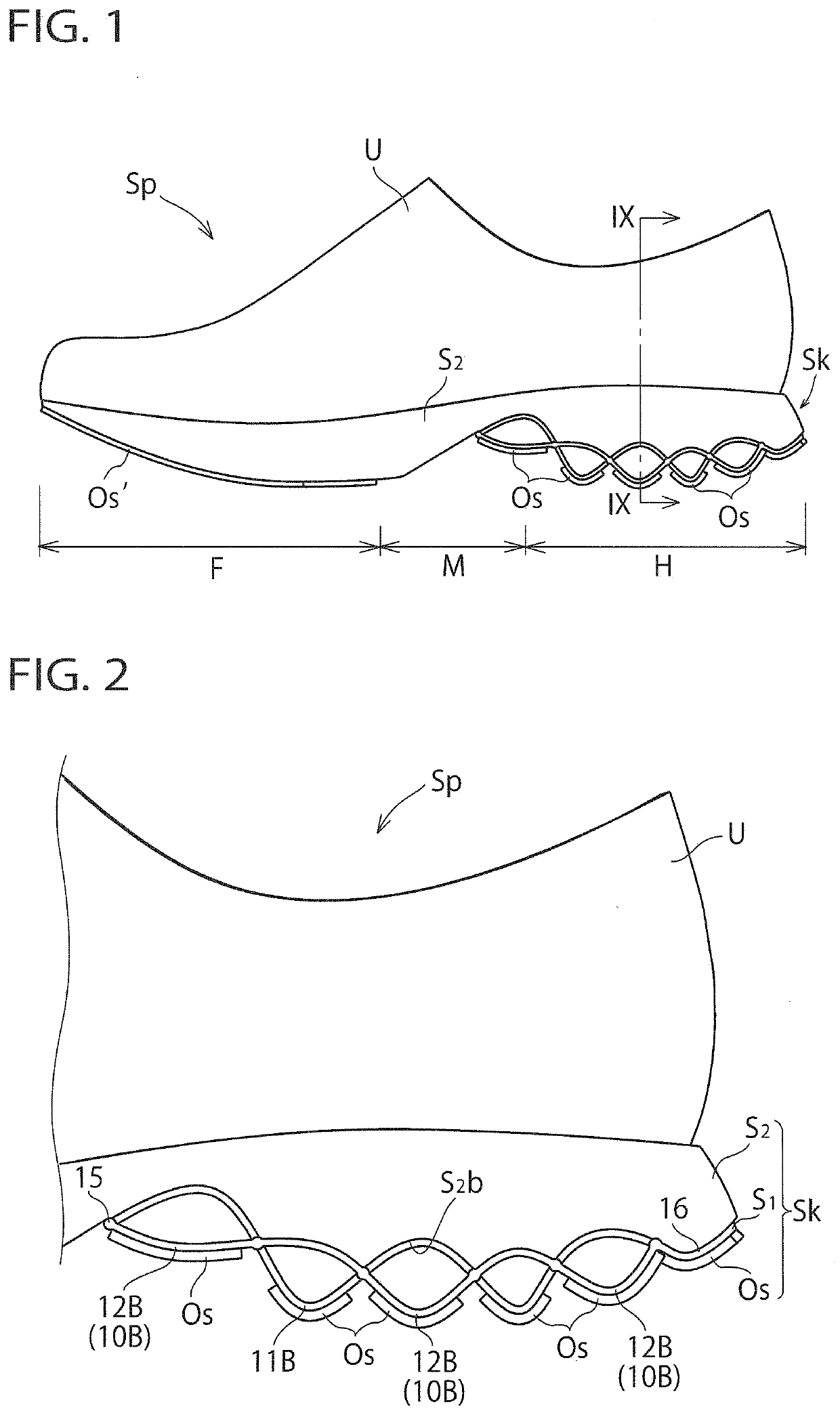
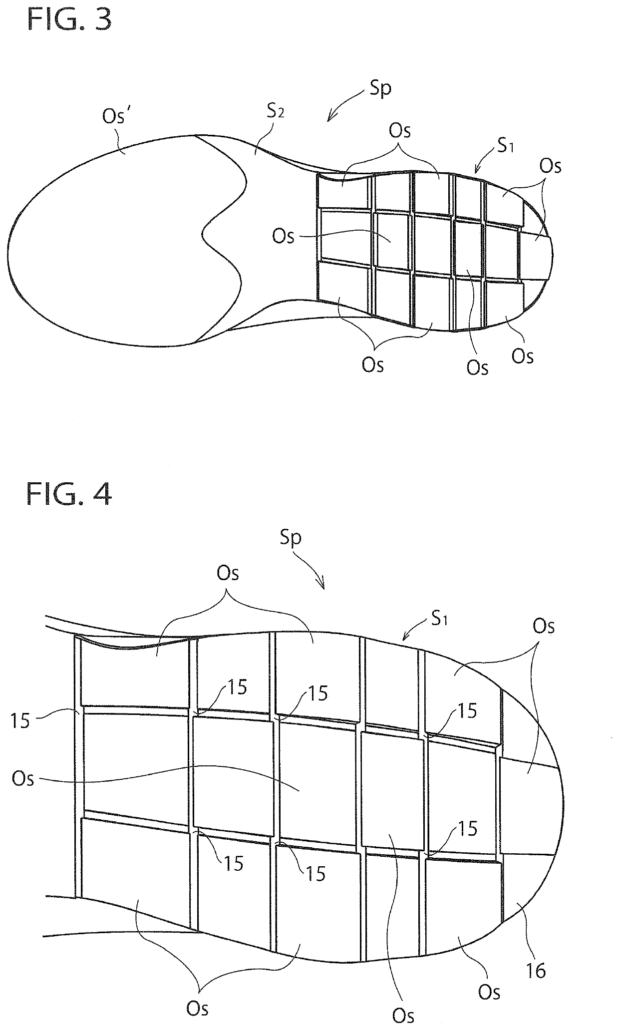
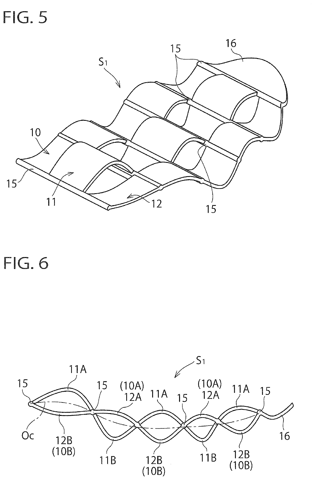
[0074]FIGS. 1 to 9 show a sole structure of a shoe according to a first embodiment of the present invention. Here, a running shoe is taken for an example, but the present invention can be also applied to a walking shoe or other sports shoe.

[0075]In the following explanation, “upward (upper side / upper)” and “downward (lower side / lower)” designate an upward direction and a downward direction, respectively, or vertical direction of the shoe, “forward (front side / front)” and “rearward (rear side / rear)” designate a forward direction and a rearward direction, respectively, or longitudinal direction (i.e. foot-length direction) of the shoe, and “a width or lateral direction” designates a crosswise direction (i.e. foot-width direction) of the shoe.

[0076]For example, in FIG. 1, a general lateral side schematic view of the shoe, “upward” and “downward” designate “upward” and “downward” in FIG. 1 respectively, or a vertical direction; “forward” and “rearward” designate “left to...

Example

Second Embodiment

[0095]FIGS. 10 to 12 show a sole structure of a shoe (or a running shoe) according to a second embodiment of the present invention. In these drawings, like reference characters indicate identical or functionally similar elements to those in the first embodiment.

[0096]As shown in FIGS. 10 to 12, this second embodiment differs from the first embodiment in that the midsole S2 has a pair of extensions S2h extending downwardly from the medial and lateral side edge portions. The extensions S2h, as shown in FIGS. 10 and 11, are provided principally at the midportion of the heel region H in this exemplification.

[0097]Provision of such extensions S2h facilitates a lateral positioning of the wavy structure S1 in installing the wavy structure S1 into the midsole S2. Also, after installation, a longitudinal central portion of the wavy structure S1 can be covered from the side, and after loading, a lateral movement of the wavy structure S1 can be restricted, thus improving landi...

Example

Third Embodiment

[0098]FIGS. 13 and 14 show a sole structure of a shoe (or a running shoe) according to a third embodiment of the present invention. In these drawings, like reference characters indicate identical or functionally similar elements to those in the first and second embodiments.

[0099]In this third embodiment, an extension S2h′ extending downwardly from the midsole S2 is provided along the entire medial and lateral side edge portions of the midsole S2 at the heel region H to the midfoot region M and provided also at the heel side edge portions. That is, according to the third embodiment, the extension S2h′ circumscribes the entire heel region H and a portion of the midfoot region M along the outer circumferential edge portions of the midsole S2 at the heel region H to the midfoot region M. The midsole S2 has a concavity formed therein to accommodate the wavy structure S1.

[0100]Provision of such an extension S2h′ causes a lateral and longitudinal positioning of the wavy str...


PUM

PropertyMeasurementUnit
Lengthaaaaaaaaaa
Thicknessaaaaaaaaaa
Structureaaaaaaaaaa

Abstract

The sole structure includes a sole body comprising a wavy structure and a midsole, and an outsole disposed below the sole body and having a ground contact surface. The wavy structure comprises a plurality of wavy extending parts that respectively extend in a wavy shape in the foot-length direction and that are disposed side by side in the foot-width direction, and a connecting portion that connects the wavy extending parts respectively in the foot-width direction. A thickness center plane of the wavy structure extends curvedly in the vertically direction toward the foot-length direction. The midsole is formed of a soft elastic member and includes a lower surface and an upper surface. The lower surface has a contact surface that the wavy structure is in contact with. The upper surface is fitted to an upper of a shoe.

Description

BACKGROUND OF THE INVENTION[0001]The present invention relates generally to a sole structure for a shoe, and more particularly, to a sole structure having a wavy structure that includes a plurality of wavy extending parts.[0002]Japanese Patent No. 3337971 (hereinafter referred to as JP '971) discloses a sole structure for an athletic shoe in which a midsole has a concave portion formed at a heel region thereof and having a shock absorbing structure installed therein (see FIGS. 27 and 28 of JP '971). The shock absorbing structure comprises a plurality of belt-shaped wavy sheets each extending in the foot-length direction and disposed side by side in the foot-width direction and a connecting portion that connects the belt-shaped wavy sheets adjacent to each other in the foot-width direction. An impact force exerted from the ground surface at the time of impacting the ground is absorbed by a compressive deformation of the belt-shaped wavy sheets and a torsional deformation of the conne...

Claims


Application Information

Patent Timeline
IPC IPC(8): A43B13/18A43B13/14A43B13/16A43B5/00A43B13/12A43B13/04
CPCA43B13/181A43B13/141A43B13/16A43B13/04A43B5/00A43B13/125A43B13/187A43B13/183A43B13/185
Inventor YOSHIDA, YOHEI
Owner MIZUNO CORPORATION
Why Eureka
Try Eureka