Method and computer program product for diagnosing a particle filter

a particle filter and computer program technology, applied in the direction of machines/engines, exhaust treatment electric control, separation processes, etc., can solve the problems of inability to direct evaluation of the correlation between the measured differential pressure p and the expected differential pressure p*, and the low differential pressure p during such an operating mode of the internal combustion engine, so as to reduce the variability of the signal, easy to evaluate, and suppress the effect of disruption-induced signal fluctuations

Active Publication Date: 2021-04-08
ROBERT BOSCH GMBH
View PDF0 Cites 3 Cited by
  • Summary
  • Abstract
  • Description
  • Claims
  • Application Information

AI Technical Summary

Benefits of technology

The patent text describes a method for accurately detecting when there is a correlation between measured and expected pressure differences or time gradients. This correlation can be used to determine if there is a defective particle filter in an exhaust gas system of an internal combustion engine. The method also includes low-pass filtering to reduce signal fluctuations and improve the accuracy of the diagnostics. The correlation between the measured and expected pressure differences or time gradients is determined using cross-correlation factors that are independent of the absolute values of the evaluated parameters. This makes it easier to evaluate the correlation and ensures reliable diagnostics results.

Problems solved by technology

For example, in the case of long freeway journeys within an approximately constant speed it is possible to directly evaluate the correlation of the differential pressure Δp with an expected differential pressure Δp*, while the time gradient d(Δp) of the differential pressure Δp during such an operating mode of the internal combustion engine is too low for reliable evaluation owing to the low dynamic excitation.
Conversely, for example in the case of a town journey with frequent changes in speed the correlation of the measured time gradient d(Δp) with the expected time gradient d(Δp*) can be used to detect a defective or removed particle filter, while the direct evaluation of the correlation between the measured differential pressure Δp and the expected differential pressure Δp* is not possible owing to the small pressure difference which is built up across the particle filter.

Method used


Image

  • Method and computer program product for diagnosing a particle filter
  • Method and computer program product for diagnosing a particle filter

Examples


Embodiment Construction

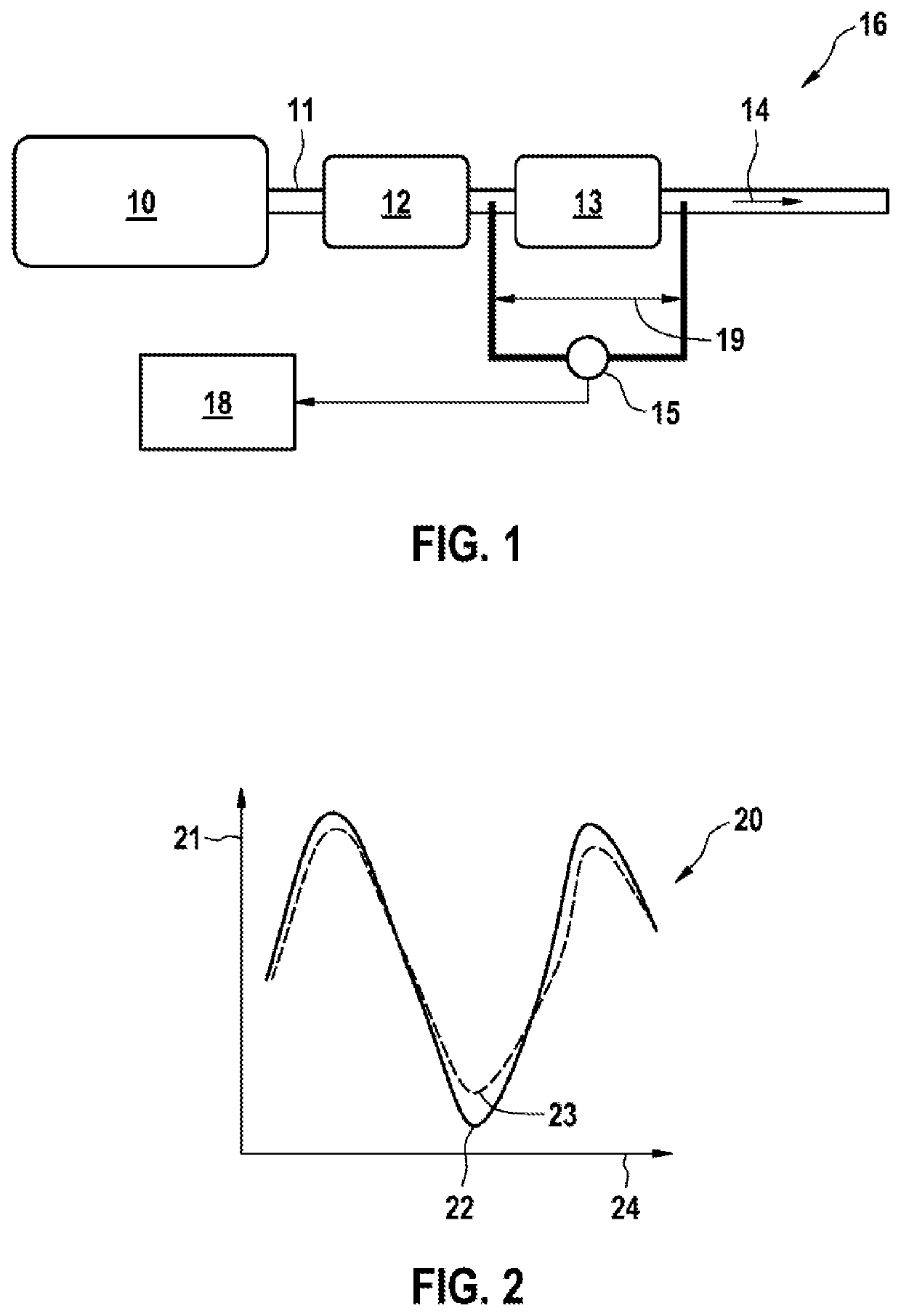
[0030]FIG. 1 shows a schematic view of the technical environment in which the invention can be used. For example an internal combustion engine 10 with an exhaust gas after-treatment system 16 is illustrated. The internal combustion engine 10 is embodied as a gasoline engine. The exhaust gas of the internal combustion engine 10 is conducted away via an exhaust train 11. The exhaust gas after-treatment system 16, which is embodied in multiple stages in the exemplary embodiment shown, is arranged along the exhaust train 11. Viewed in the direction of flow of the exhaust gas (exhaust gas flow 14), firstly a catalytic converter 12 is provided, embodied here as a three-way catalytic converter. The catalytic converter 12 has a particle filter 13 connected downstream of it. In the selected basic illustration, the exhaust gas after-treatment system 16 has further components (not shown), such as exhaust gas probes and further sensors whose signals are fed to an engine controller (electronic c...


PUM

PropertyMeasurementUnit
differential pressureaaaaaaaaaa
differential pressure Δpaaaaaaaaaa
differential pressure Δp*aaaaaaaaaa

Abstract

The invention relates to a method and a computer program product for identifying an absent or defective particle filter in an exhaust gas treatment system of an internal combustion engine, in particular a petrol engine, wherein in order to monitor the particle filter a pressure difference between the inlet and the outlet of the particle filter is measured and evaluated. In that context, it is provided that, depending on the operating parameters of the internal combustion engine and / or of the exhaust gas treatment system, a correlation of the measured pressure difference across the particle filter compared to an expected pressure difference for an intact reference particle filter, or a correlation of the gradient, with respect to time, of the measured pressure difference to an expected gradient, with respect to time, of the expected pressure difference for an intact reference particle filter, is determined, and that, in the event of high correlation it is concluded that a particle filter is present and intact, and in the event of low correlation it is concluded that a particle filter is absent or defective. The method makes it possible to identify an absent or defective particle filter under many operating conditions of the internal combustion engine, even in the case of very low absolute pressure differences, as is in particular the case with petrol particle filters.

Description

BACKGROUND OF THE INVENTION[0001]The invention relates to a method for detecting a removed or defective particle filter in an exhaust gas after-treatment system of an internal combustion engine, in particular of a gasoline engine, wherein in order to monitor the particle filter a differential pressure Δp between the inlet and the outlet of the particle filter is measured and evaluated.[0002]The invention also relates to a computer program product for carrying out the method.[0003]Emissions legislation, in particular in the USA and in Europe, stipulates limiting values for the emission of particle mass and also numbers and concentrations of particles for the operation of internal combustion engines. In addition to the emission limiting values, diagnostic limiting values are also specified, the exceeding of which has to trigger the indication of a fault. In a vehicle which is driven by the internal combustion engine, for this purpose diagnostic functions are implemented which monitor ...

Claims


Application Information

Patent Timeline
Patent Type & Authority Applications(United States)
IPC IPC(8): F01N11/00F01N3/021F01N3/24F01N13/00B01D46/44B01D46/00B01D53/94
CPCF01N11/002F01N3/021F01N3/24F01N13/008B01D2279/30B01D46/0086B01D53/9477F01N2370/02F01N2560/08B01D46/446F01N11/00F01N2550/04F01N2550/24F01N2900/0416F01N2900/08Y02T10/40
Inventor BAUMANN, THOMASLIAN, YUNJIE
Owner ROBERT BOSCH GMBH
Why Eureka
Try Eureka