Redundant Drive Orbittally Driven Electric Ducted Fan Producing Torque with Lower Electric Current Drawn

a technology of electric ducted fans and torque, applied in the direction of machines/engines, liquid fuel engines, transportation and packaging, etc., can solve the problems of catastrophic failure of one circuit, and achieve the effects of reducing the size of the electro-magnet, and reducing the weight of the fan

Active Publication Date: 2021-04-08
NEWTON STEPHEN T +1
View PDF0 Cites 0 Cited by
  • Summary
  • Abstract
  • Description
  • Claims
  • Application Information

AI Technical Summary

Benefits of technology

This patent describes a device with a unique design that allows for high-availability and robust operation. It uses a feedback system to ensure that each fan blade is driven independently, so if one circuit fails, another circuit can still operate. The device also has multiple fan stages that can be placed in line and rotated in opposite directions to increase pressure and improve performance. This technology provides a reliable and efficient solution for a variety of applications.

Problems solved by technology

The redundancy of drives allowing for high availability operations where the failure of one circuit could be catastrophic.

Method used


Image

  • Redundant Drive Orbittally Driven Electric Ducted Fan Producing Torque with Lower Electric Current Drawn
  • Redundant Drive Orbittally Driven Electric Ducted Fan Producing Torque with Lower Electric Current Drawn

Examples


Embodiment Construction

Integrated Fan Rotor Assembly

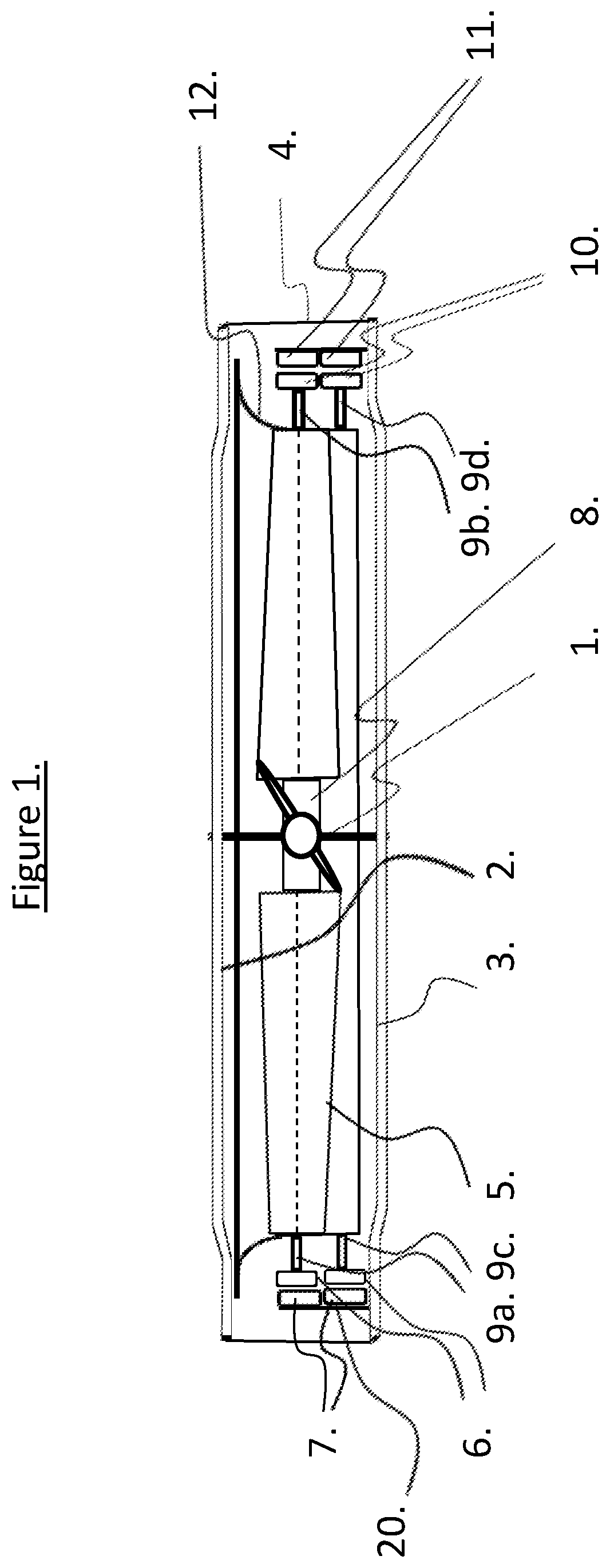
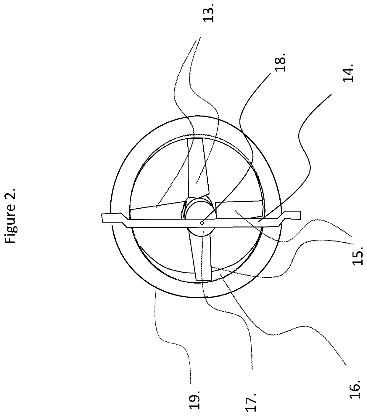
[0025]Referring to FIGS. 1 and 2, through a center line drawn from the air inlet through the air outlet is a main axle 1 and 18. This axle is retained in that position by sufficient support as determined by the designer. This support can be a front and rear 14 if the fan is mounted vertically or top and bottom supports 2 and 3.

[0026]The main axle 1 and 18 needs to be stiff enough to resist unbalanced rotational forces applied during continuous operation. If the environment in which the fan operates is subject to foreign object damage the designer will have to balance increased structure to account for such risk against the safety issues involved, cost of manufacture, and cost of operation.

[0027]Fixed linearly on the main axle 1 and 18 and located at the center point of the stator assembly 20, is a fan blade mounting hub 8 and 17 (FIGS. 1 and 2). This hub is so named as the fan blades 5, 13, and 15 are mounted are themselves mounted on this hub. Weight is...


PUM


Abstract

The ideal design for a redundant orbitally driven electric ducted fan that can replace a family of current propeller and motor combinations in electric ducted fan designs by meeting air flow and pressure requirements while drawing less electric current to rotate and thus produce the required flow not only would reduce cost of operation over the life of the fan but opens new possibilities for electric powered vertical takeoff and landing vehicles with redundant drives improving safety of operation. The entry of flying machines using propellers and lifting fans such as hover bikes and quadcopters, manned or unmanned is driving a need to re-examine the application of force applied to rotate these fans to achieve a reduction in aircraft weight and increase flying time for a given battery charge or load of fuel.

Description

CROSS REFERENCE TO RELATED APPLICATIONS[0001]This application claims priority from U.S. Provisional Application Ser. No. 62 / 755,760 filed Nov. 5, 2018.STATEMENT REGARDING FEDERALLY SPONSORED RESEARCH OR DEVELOPMENT[0002]This invention was not made with U.S. Government support.BACKGROUND PRIOR ART[0003]The present invention is directed generally to electric ducted fans (EDF) used currently in the primarily as propulsion systems for aircraft but can also replace axial flow fans employed in agricultural and HVAC applications. In particular, the present invention relates to a new class of EDFs which are obitally driven fans (ODF).[0004]In electric ducted fans an electric motor drives a propeller inside a close tolerance duct. The duct reduces losses in thrust from the tips of the propellers, making it more efficient and also reduces noise.[0005]To obtain redundancy driving a lifting fan for use in aircraft or HVAC applications requiring high availability, a designer must employ multiple...

Claims


Application Information

Patent Timeline
IPC IPC(8): F04D29/54F04D25/06F04D25/08F04D29/38
CPCF04D29/545F04D29/38F04D25/08F04D25/06F04D25/0606F04D29/526F04D29/326B64U30/26B64C27/20B64U50/19B64C27/16
Inventor NEWTON, STEPHEN TNEWTON, II, STEPHEN T.
Owner NEWTON STEPHEN T
Why Eureka
Try Eureka