
Method for producing a connection element, and connection element

a technology of connection elements and connection elements, which is applied in the direction of pivotal connections, mechanical devices, transportation and packaging, etc., can solve the problems of increasing the proportion of unsprung masses, affecting driving characteristics, and affecting the fuel consumption of the motor vehicle concerned, so as to simplify the production process

Inactive Publication Date: 2021-04-08
ZF FRIEDRICHSHAFEN AG
View PDF0 Cites 0 Cited by
  • Summary
  • Abstract
  • Description
  • Claims
  • Application Information

AI Technical Summary

Benefits of technology

The present invention simplifies the production process of a connection element that has a hybrid structure, which involves combining metallic and plastic components. The invention uses an arrangement of at least two profile sections held in position with interlock by at least one fixing element. This simplifies the production process and allows for easier handling of the connection element during overmolding. The design of the profile sections as identical parts reduces fabrication costs and allows for easier arrangement. The use of the fixing element prevents the two profile sections from being pushed apart or towards each other. The technical effects of the invention include increased precision in positioning functional components and retaining advantages of the hybrid structure like low weight and inexpensive production.

Problems solved by technology

An essential disadvantage of connection elements made of metal is that they are quite heavy, usually requiring additional finish machining during their production and also measures to protect them against corrosion.
The higher weight increases the proportion of unsprung masses, which has negative consequences for the driving characteristics and also for the fuel consumption of the motor vehicle concerned.

Method used


Image

  • Method for producing a connection element, and connection element
  • Method for producing a connection element, and connection element
  • Method for producing a connection element, and connection element

Examples


Embodiment Construction

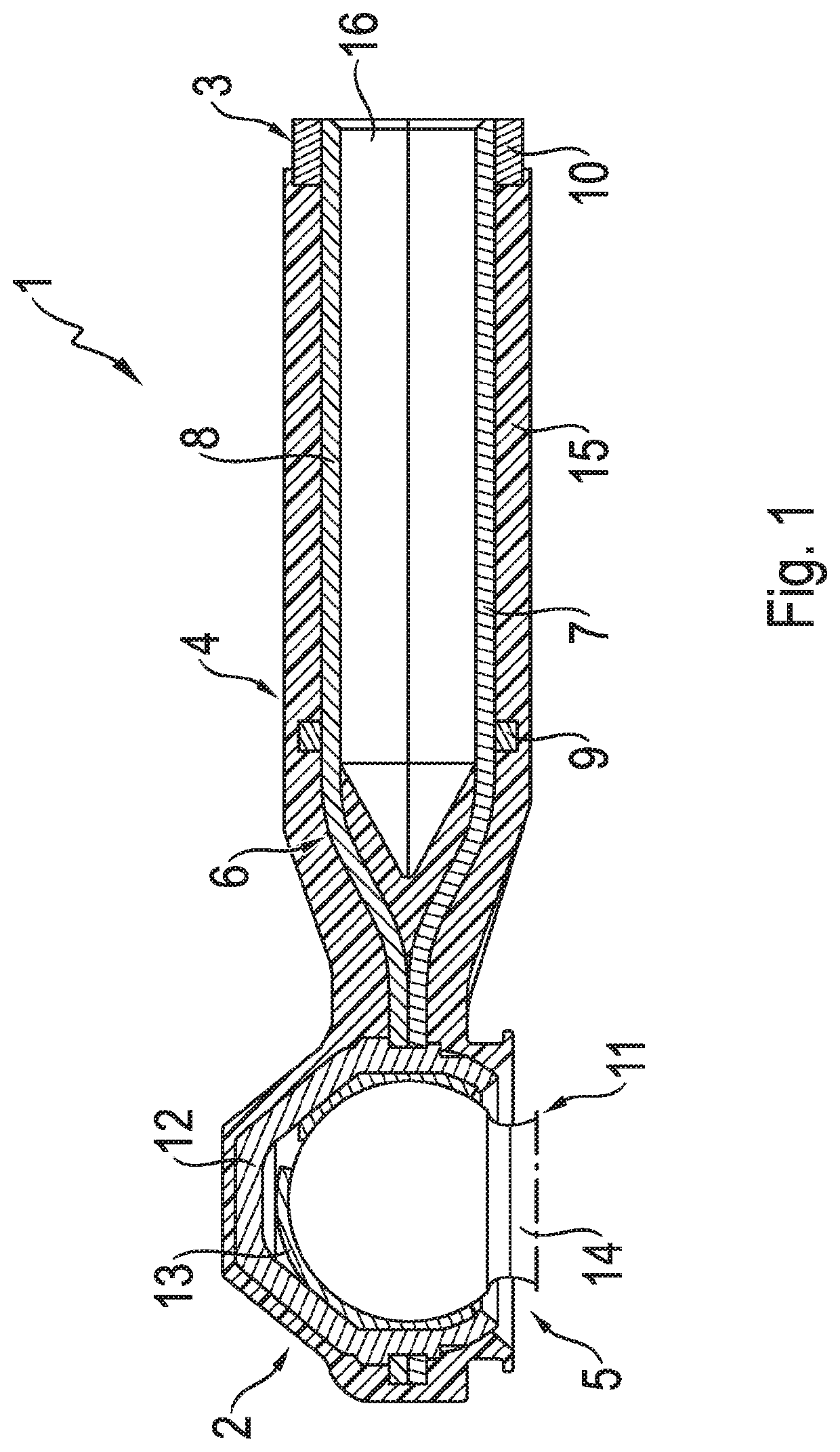
[0038]FIG. 1 shows a schematic representation of a connection element 1 in the form of an outer track-rod joint. The connection element 1 is divided into a number of portions, namely a joint portion 2, a connection portion 3, and a central portion 4 which connects the joint portion 2 and the connection portion 3 to one another. The joint portion 2 serves to accommodate a joint component 5 whereas the connection portion 3 serves to form an adjustable-length arrangement on a track rod (not shown).

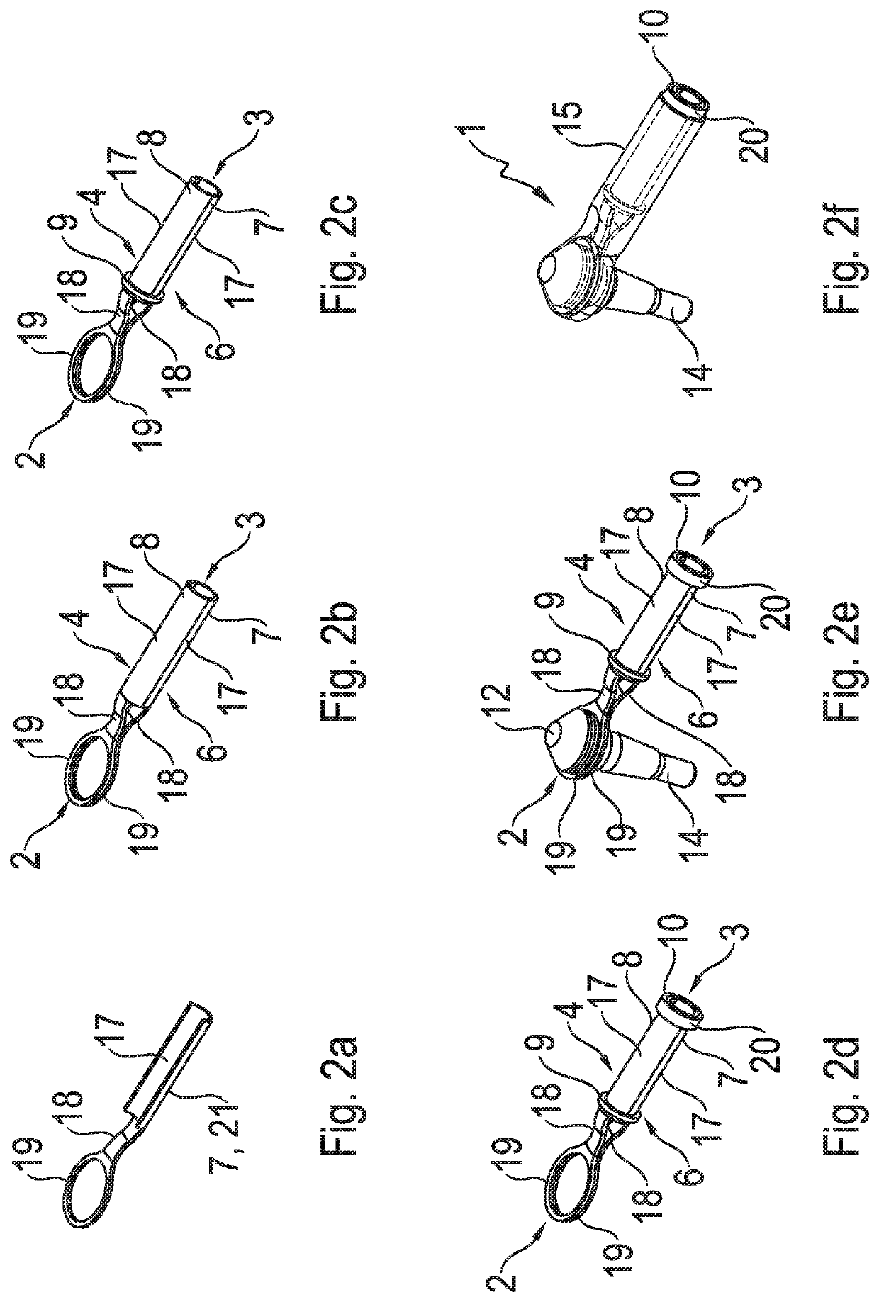
[0039]The connection element is formed of a partially cylindrical profile element 6. The profile element 6 comprises at least one first profile section 7 and at least one second profile section 8. The first profile section 7 and the second profile section 8 are each partially half-shell shaped and are arranged in mirror-image relationship to one another. In the example embodiment illustrated the two profile sections 7 and 8 which form the profile element 6 are made as two separate semifinishe...


PUM

PropertyMeasurementUnit
Timeaaaaaaaaaa

Abstract

A method for producing a connection element (1, 30), in particular for an articulated connection of components arranged in a chassis. The connection element (1, 30) is formed by a profile element (6, 31) which includes a joint portion (2), for accommodating a joint component (5), a central portion (4), and a connection portion (3). The profile element (6, 31) is formed by an arrangement of at least one first profile section (7, 32) and at least one second profile section (8, 33), which are held in position, with interlock, by at least one fixing element (9, 10), a joint component (5) is inserted, into the joint portion (2) so formed, and the profile element (6, 31) and the joint component (5) are partially overmolded with a plastic material.

Description

[0001]This application is a National Stage completion of PCT / EP2018 / 059095 filed Apr. 10, 2018, which claims priority from German patent application serial no. 10 2017 208 096.5 filed May 15, 2017FIELD OF THE INVENTION[0002]The invention relates to a method for producing a connection element, in particular for the articulated connection of components arranged in a chassis, wherein the connection element is formed from a profile element which comprises a joint portion for accommodating a joint component, a central portion, and a connection portion.BACKGROUND OF THE INVENTION[0003]In addition the invention relates to a connection element, in particular for the articulated connection of components arranged in a chassis, wherein the connection element comprises a partially cylindrical profile element with a joint portion for accommodating a joint component, a central portion, and a connection portion.[0004]Track rods connect the rack of a steering system to wheel carriers of a motor veh...

Claims


Application Information

Patent Timeline
IPC IPC(8): F16C11/06B60G7/00B62D7/20
CPCF16C11/0619F16C11/0685B62D7/20B60G7/005F16C2326/24F16C2326/05B60G2204/416B60G2204/422B60G2206/017B60G2206/11B60G2206/14B60G2206/8102B60G2206/8103B62D7/166B29C45/1671B29C45/0001B60G2206/81012
Inventor NACHBAR, FRANKBONKOWSKI, OLIVERDOBBELHOFF, FRANK
Owner ZF FRIEDRICHSHAFEN AG
Learn More