Additive manufacturing optimized first stage vane

Active Publication Date: 2021-04-15
POWER SYST MFG LLC
View PDF0 Cites 0 Cited by
  • Summary
  • Abstract
  • Description
  • Claims
  • Application Information

AI Technical Summary

Benefits of technology

The present invention is about an improved airfoil for turbine vanes. The airfoil has a specific shape based on Cartesian coordinate values, including X, Y, and Z. The technical effects of this design include improved aerodynamic performance and reduced operational costs. Other embodiments involve vane assemblies and first stage blades with the same improved design. Overall, the invention provides a more efficient and cost-effective solution for airfoil design in turbine engines.

Problems solved by technology

The stationary turbine vanes and rotating turbine blades have been known to be limited in power output by a variety of operating conditions.

Method used


Image

  • Additive manufacturing optimized first stage vane
  • Additive manufacturing optimized first stage vane
  • Additive manufacturing optimized first stage vane

Examples


Embodiment Construction

[0013]The subject matter of the present invention is described with specificity herein to meet statutory requirements. However, the description itself is not intended to limit the scope of this patent. Rather, the inventors have contemplated that the claimed subject matter might also be embodied in other ways, to include different components, combinations of components, steps, or combinations of steps similar to the ones described in this document, in conjunction with other present or future technologies.

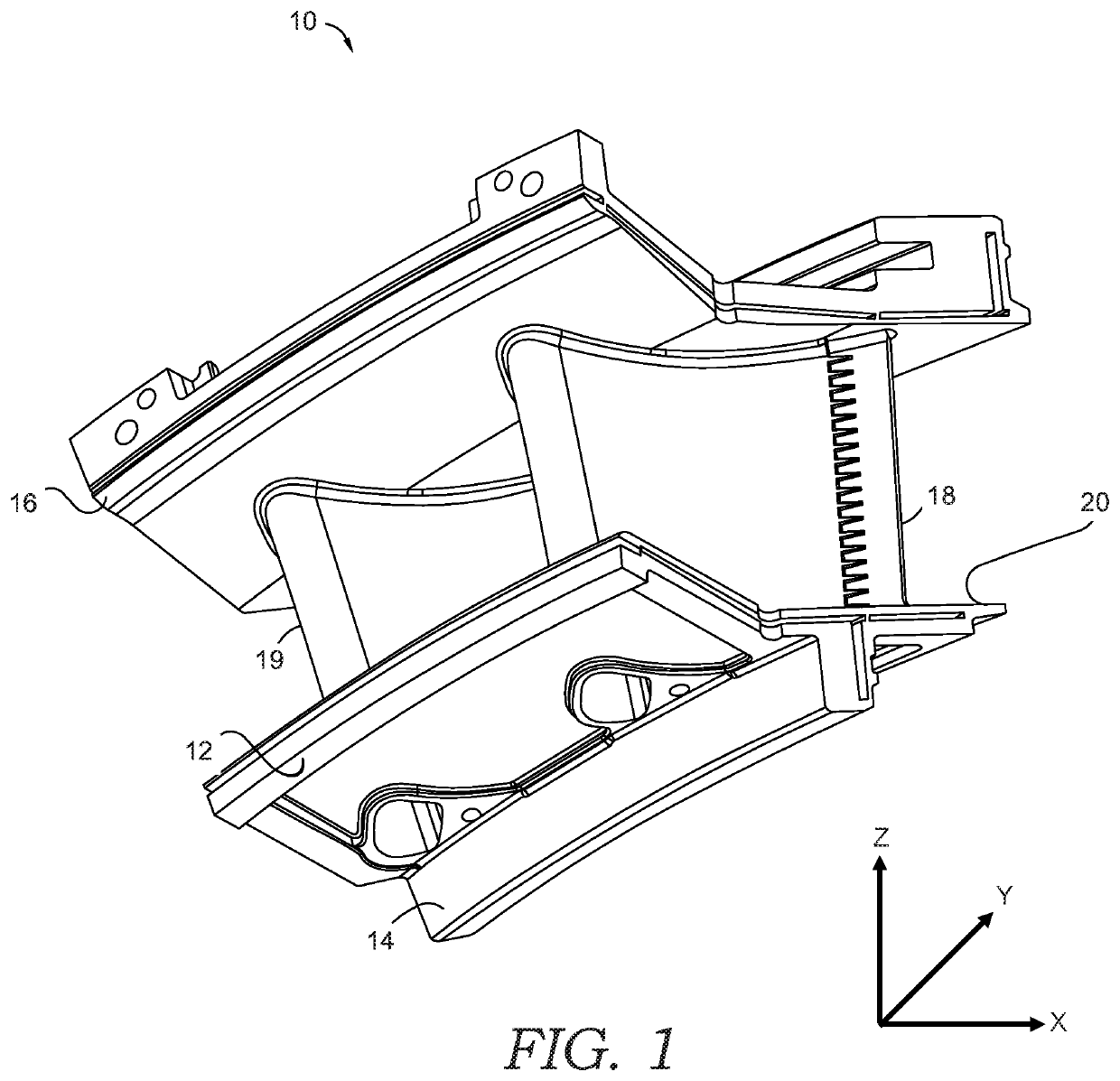
[0014]FIG. 1 shows a vane assembly 10 of a gas turbine engine that incorporates a plurality of vane airfoils 18,19 having an outer profile according to embodiments of the present invention. The vane assembly 10 generally includes an inner platform 12, an inner rail 14, an outer platform 16, and the plurality of airfoil vanes 18, 19. The airfoil vanes 18, 19 extend between the inner platform 12 and the outer platform 16 and, more particularly, extend from a radially outwardly facing...


PUM

PropertyMeasurementUnit
Lengthaaaaaaaaaa
Thicknessaaaaaaaaaa

Abstract

An airfoil and turbine vanes and vane assemblies incorporating the same. The airfoil has an uncoated profile substantially in accordance with Cartesian coordinate values of X, Y, and Z as set forth in Table 1, carried to four decimal places. The Z values refer to a percentage of the radial span of the airfoil measured radially from a radially outwardly facing surface of the inner platform. The turbine vane includes an inner platform, an outer platform, and an airfoil such as the one discussed above extending radially outward from the inner platform toward the outer platform. And the vane assembly includes an inner platform, an outer platform, and two or more first stage vanes extending from the inner platform to the outer platform. Each of the two or more first stage vanes include an airfoil as discussed above.

Description

TECHNICAL FIELD[0001]The present invention generally relates to gas turbine engines. More specifically, aspects of the invention are directed to a profile of a turbine vane such as that of a first stage turbine blade of a gas turbine engine.BACKGROUND OF THE INVENTION[0002]A typical gas turbine engine comprises a compressor, at least one combustor, and a turbine, with the compressor and turbine coupled together through an axial shaft. In operation, air passes through the compressor, where the pressure of the air increases and then passes to a combustion section, where fuel is mixed with the compressed air in one or more combustion chambers and ultimately ignited. The hot combustion gases then pass into the turbine and drive the turbine. As the turbine rotates, the compressor turns since they are coupled together along a common shaft. The turning of the shaft also drives a generator for electrical applications. The engine must operate within the confines of the environmental regulati...

Claims


Application Information

Patent Timeline
IPC IPC(8): F01D5/28F01D9/04
CPCF01D5/28F01D9/04F05D2300/611F05D2300/17F05D2220/32F05D2230/30F05D2250/74
Inventor VOGEL, GREGORY EDWINMCNALLY, JOSHUA ROBERTKITAIGOROD, VLADIMIR
Owner POWER SYST MFG LLC
Why Eureka
Try Eureka