Portable intermittent fault detector

a fault detector and portable technology, applied in the field of electronic devices, can solve the problems of damage or loss to the vehicle, damage to delicate electronic components, and other types of damage, and achieve the effect of strengthening rigidity and/or impact resistan

Active Publication Date: 2021-04-15
UNIVERSAL SYNAPTICS CORP
View PDF0 Cites 1 Cited by
  • Summary
  • Abstract
  • Description
  • Claims
  • Application Information

AI Technical Summary

Benefits of technology

[0012]In one aspect, a portable diagnostic system according to this disclosure may passively transfer heat away from the electronic components of the portable diagnostic system. In another aspect, a portable diagnostic system according to this disclosure may include a switchable power supply. According to another aspect, the electronic components of a portable diagnostic system may be arranged in a manner that reduces or eliminates noise generated by the portable diagnostic system. In yet another aspect, a configuration of the portable diagnostic system may limit the forces to which the delicate test modules of the portable diagnostic system may be exposed.
[0015]The chassis and many of the electronic components may be carried by a bottom portion of the case. A configuration of the chassis, along with configurations of various electronic components carried by the chassis, may enable the chassis to passively and efficiently convey heat away from the electronic components of the portable diagnostic system. More specifically, the chassis may comprise a thermally conductive plate (e.g., an aluminum plate, etc.) that serves as a heat sink for various other components, including other thermally conductive elements of the chassis and heat-generating electronic components, of the portable diagnostic system. A mass of the thermally conductive plate may enable it to absorb heat quickly from the electronic components. An area on an opposite, second side (e.g., a bottom side, etc.) of the thermally conductive plate may enable it to dissipate heat into a space between the second side of the thermally conductive plate and an interior surface of the base of the enclosure. The rate at which heat dissipates from the thermally conductive plate corresponds to the ability of the thermally conductive plate to continue absorbing heat from the electronic components of the diagnostic system without exposing the electronic components to undesirably high levels of heat.
[0018]Noise generated by the portable diagnostic system may be minimized, substantially eliminated (e.g., by eliminating all ribbon connectors, leads, and other intermediate conductive elements as sources of noise, etc., while one or more electronic components may continue to generate noise) in a variety of ways. As an example, minimizing the number of noise-generating electronic components may reduce the overall level of noise produced by the portable diagnostic system, as may the selection of electronic components (e.g., a power supply, etc.) that generate little or no noise, or that are substantially noise-free. As another example, the lengths of all of the power leads and ribbon connectors of the portable diagnostic system may be minimized. The length of each lead and / or ribbon connector may be short enough to prevent it from acting as a quarter wavelength antenna, which may reduce edges in waveforms of the signals transmitted by the leads and / or conductive elements of the ribbon connectors, and, therefore, may eliminate the generation and / or transmission of noise, or EMI. Each ribbon connector of the portable diagnostic system may have a length of about 4 inches (10.2 cm) or less or even a length of about 3 inches (7.6 cm) or less. The electronic components of the portable diagnostic system may be oriented and arranged in a manner that minimizes the length of each ribbon connector, and which may minimize the collective lengths of all of the ribbon connectors. Additionally, the electronic components of the portable diagnostic system may be oriented and arranged in a manner that provides for direct connections between electronic components, and, thus, eliminates the need for folding any ribbon connector at a non-straight angle, such as a right angle or an approximate right angle, etc.).
[0020]As an example, the test module assembly may absorb impacts and other forces in a manner that limits the gravitational force equivalents, or g-forces (go), experienced by its circuit board, test modules, and connections to non-damaging levels (i.e., g-forces that these delicate components and features are known to be able to withstand). The test module assembly may be capable of absorbing absorb impacts and other forces that generate a g-force of 20 go or more, while the delicate components and features of the test module assembly experience a g-force of about 10 go or less. In a specific embodiment, a configuration of the test module assembly may enable the portable diagnostic system experience g-forces of up to 20 go while limiting the g-forces experienced by the delicate electronic components and features of the test module assembly to experience a g-force of 10 go or less. In such an embodiment, the delicate electronic components and features of the test module assembly may be able to withstand repeated drops of the portable diagnostic system from a height of up to four (4) feet.
[0021]The test module assembly may include an outer support, an inner frame, and a plurality of isolators between the outer support and the inner frame. The outer support may comprise a rigid structure. The inner frame may also comprise a rigid structure. These elements may be arranged in such a way that the inner frame and the circuit boards and test modules it carries may float relative to the outer support and, thus, relative to the chassis and the enclosure of the portable diagnostic system. For example, the isolators may non-rigidly secure the inner frame and, thus, the inner assembly of the test module assembly to the outer support of the test module assembly and, in some embodiments, to the chassis and / or the enclosure of the portable diagnostic system. Each isolator, as well as the distances between the outer surfaces of the inner assembly and inner surfaces of the outer support, the chassis, and the cover that oppose, or face, the outer surfaces of the inner assembly, may enable the inner assembly to travel in any direction within the outer support.
[0022]Test module boards of the test module assembly may be assembled with the inner frame and with one another in a manner that enhances the rigidity and / or the impact resistance of an inner assembly of the test module assembly. As an example, the inner frame may at least partially surround an outer periphery of a plurality of test module boards that are superimposed, or stacked, relative to one another in a spaced apart relation to each other. The boards of the inner assembly may be rigidly secured to the inner frame. Spacers may separate adjacent test module boards from each other, but rigidly secure them to each other.

Problems solved by technology

Nevertheless, electrical connections between the components of electrical systems are known to degrade over time, causing the electrical systems of which they are a part to malfunction.
The delicate electronic components are also subject to degradation and other types of damage.
Faults in and failure of a vehicle's electrical systems and the consequent malfunction of the vehicle can result in damage or loss to the vehicle, as well as loss of life, both of which are very costly.
While constant faults are relatively easy to diagnose and repair, intermittent failures are random in nature and, thus, they are extremely difficult to detect, isolate, and resolve.
In complex electrical systems with multiple circuits, the odds that a random, elusive intermittent fault will occur in a failing circuit at the exact moment a serial test method is used to scan that circuit are infinitesimally small.
Thus, although serial test methods provide stable readings from circuits with constant faults, they have proven fundamentally ineffective for detecting randomly occurring, low-level, intermittent faults.
Oscilloscopes are generally able to detect intermittent faults; however, oscilloscopes are only useful for testing one circuit at time.
Thus, they are not useful for testing for intermittent faults in complex electrical systems with multiple circuits.
In addition, oscilloscopes require that an electrical stimulus be applied to the circuit under test, making them largely impractical and unsuitable for complex electrical systems that include hundreds or thousands of circuits and connection points.
While the IFDIS 2.0 diagnostic system detects intermittent faults in complex electrical systems with a high degree of accuracy, it is also very expensive.
Despite its incorporation of effective, state-of-the-art intermittent fault detection technology, as demonstrated through repeated testing, design issues in various iterations of the prototypes of the VOYAGER portable diagnostic system have led to quality issues that have prevented its commercialization.
In particular, the small form factor of the various prototypes of the VOYAGER portable diagnostic system led to temperature management issues, power management issues, and the generation of noise (i.e., unwanted disturbances in electrical signals; electromagnetic interference (EMI)).
Complex power management systems add to the overall heat and noise generated by the prototypes of the VOYAGER portable diagnostic system, while failing to supply constant voltages to the electronic components of the portable diagnostic system.
The numerous electronic components and the use of long ribbon connectors (e.g., up to about 15 inches (38.1 cm) in length) generate undesirable levels of noise, which was addressed by lining the enclosures of later prototypes of the VOYAGER portable diagnostic system with copper, adding to their complexity and expense.
In addition, the portability of the various prototypes of the VOYAGER portable diagnostic system and the impacts that occur while transporting them, in combination with the manner in which test modules of the portable diagnostic system are assembled, have resulted in undesirable mechanical failure rates and the concomitant increased likelihood of damage to the relatively delicate test modules of the prototype portable diagnostic systems.
The undesirable mechanical failure rates are believed to result from flexibility in the manner in which the boards that carry the test modules were assembled with each other and with other components (e.g., a chassis, etc.) of the VOYAGER portable diagnostic system.

Method used


Image

  • Portable intermittent fault detector
  • Portable intermittent fault detector
  • Portable intermittent fault detector

Examples


Embodiment Construction

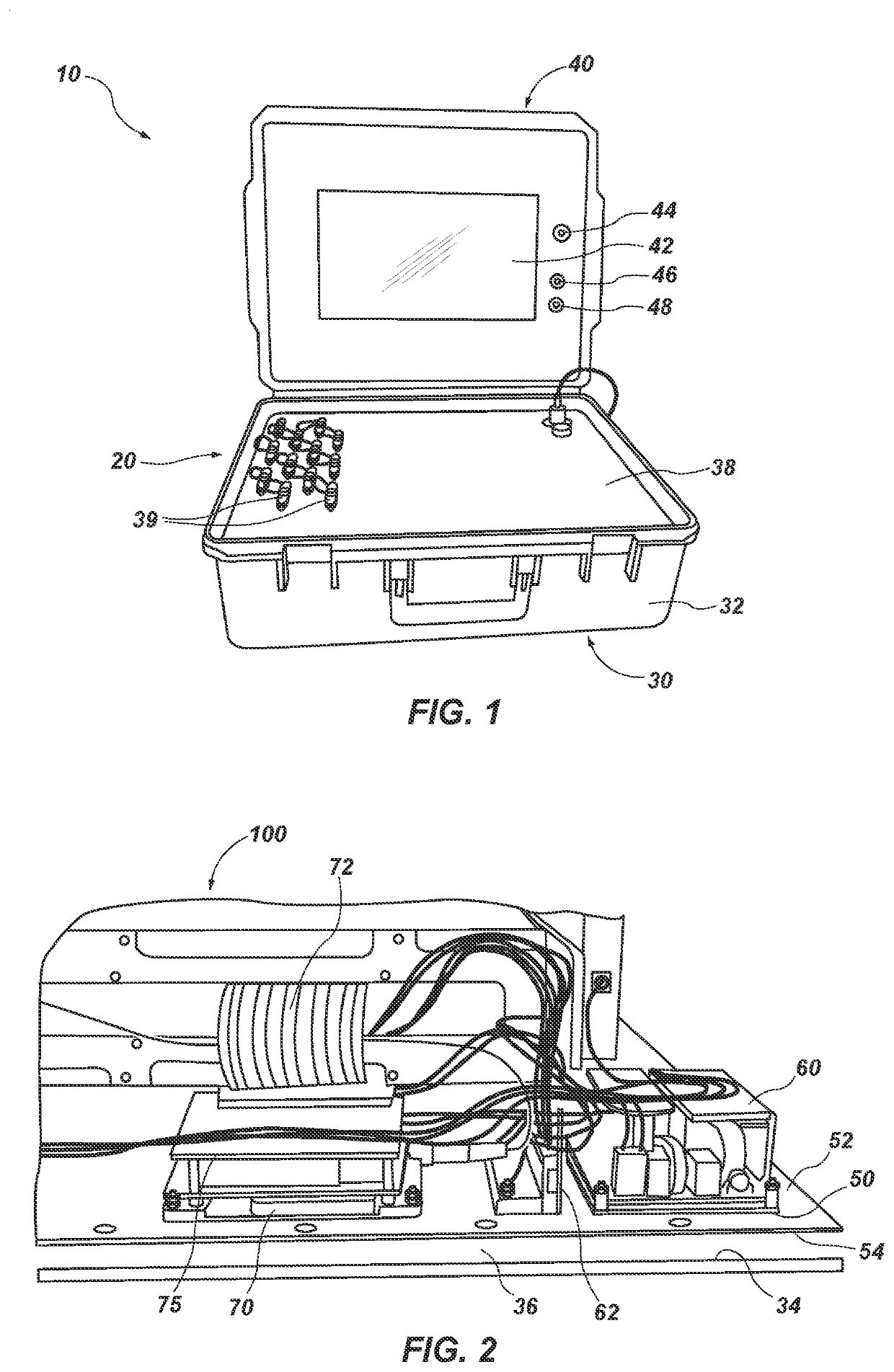
[0033]As illustrated by FIG. 1, a portable diagnostic system 10 according to this disclosure may include an enclosure 20 with a base 30, or a bottom portion, and a lid 40, or a top portion. FIG. 1 shows the lid 40 in an open arrangement over the base 30. The lid 40 may also be closed over the base 30 (e.g., pivotally by way of hinges, etc.).

[0034]The enclosure 20 may comprise any suitable type of case. In some embodiments, the case may have a design (e.g., comprise a material, include at least one feature, etc.) that enables it to protect the delicate electronic components of the portable diagnostic system. In a specific embodiment, the enclosure 20 may comprise a case of the type available from Pelican Products, Inc., of Torrance, Calif. Such an enclosure 20 may comprise injected molded plastic and include a gasket that enables it to seal when the lid 40 is secured in place over the base 30. In some embodiments, the enclosure 20 may be watertight and / or airtight. The enclosure 20 m...


PUM


Abstract

A portable intermittent fault detector includes an enclosure that carries electronics and a display. The electronics are selected, arranged, and connected in a manner that minimizes noise, including noise that could interfere with an ability of the portable intermittent fault detector to detect intermittent faults in complex electrical systems. The portable intermittent fault detector also includes a passive heat management system hat conveys heat away from the electronics. In addition, a test module assembly of the portable intermittent fault detector includes an inner assembly with test module boards that are rigidly secured to one another and an outer support that carries the inner assembly in a manner that absorbs impacts and other forces on the portable intermittent fault detector.

Description

CROSS-REFERENCE TO RELATED APPLICATION[0001]A claim for priority to the Aug. 23, 2019 filing date of U.S. Provisional Patent Application No. 62 / 891,266, titled PORTABLE INTERMITTENT FAULT DETECTOR, is hereby made pursuant to 35 U.S.C. § 119(e) (“the '266 Provisional Application”). The entire disclosure of the '266 Provisional Application is hereby incorporated herein.TECHNICAL FIELD[0002]This disclosure relates generally to electronic devices and, more specifically, to portable electronic devices. Even more specifically, this disclosure relates to electrical testers, including testers that can detect faults in electrical systems, such as the complex electrical systems of aircraft. More particularly, this disclosure relates to portable electrical fault detectors, including portable intermittent fault detectors.RELATED ART[0003]A variety of sophisticated vehicles, including, without limitation, airplanes, helicopters, unmanned aerial vehicles (UAVs), rockets, satellites, ships, tanks,...

Claims


Application Information

Patent Timeline
Patent Type & Authority Applications(United States)
IPC IPC(8): G01R31/52G01R31/69G01R31/54G01R31/00
CPCG01R31/52G01R31/008G01R31/54G01R31/69
Inventor KELLY, PATRICK B.KELLY, JAYSON
Owner UNIVERSAL SYNAPTICS CORP
Why Eureka
Try Eureka