Method for crane assembly

a crane and assembly technology, applied in the direction of cranes, load-engaging elements, transportation and packaging, etc., can solve problems such as unauthorised access to the construction si

Active Publication Date: 2021-04-22
LIEBHERR WERK BIBERACH
View PDF0 Cites 1 Cited by
  • Summary
  • Abstract
  • Description
  • Claims
  • Application Information

AI Technical Summary

Benefits of technology

[0004]Larger top slewing cranes are usually operated via the control station in the crane cab. This control station provides the advantage that the crane operator usually has a good overview of the construction site and sufficient visual contact with the picked-up load at all times. The control station strongly binds the crane operator to the machine, since the operator will accept the exhausting and time-consuming descent from the crane only in longer interruptions.
[0007]A system for central control of one or more cranes is proposed, wherein the system includes at least one crane and at least one central control station. The at least one crane includes one or multiple image sensors, which are configured to observe a picked-up load, at least part of the crane surroundings, as well as at least part of the crane structure. Preferably, the arrangement of the image sensors allows detecting all movable crane components, ideally of the entire crane structure. For example, image sensors are provided, which are attached to a trolley and / or a slewing platform and / or a load hook, or which can at least detect these crane components. The introduction of external screens additionally improves the crane operator's vision.
[0009]By arranging the individual image sensors at the crane in a manner according to the invention, a sufficient field of view results for the crane operator in order to always be able to observe the required components of the crane or of the environment. There is no need for the crane operator to have direct visual contact with the crane or the surroundings, the observing of information displayed on the display element is sufficient. The positioning of the control station is thus no longer bound to limiting conditions, but instead, it is sufficient that a stable communication link with as little delay as possible can be ensured. In particular, it is thereby possible to integrate the central control station into an office container or a similar building, which is preferably centrally placed on a large construction site. The construction machines or cranes to be controlled at the large construction site can be remote-controlled from this location.
[0010]In order to enable a realistic monitoring of the crane structure, the surroundings and the load, it is particularly advantageous if the individual image sensors are formed as stereo cameras. As a result, stereoscopic visual information can be generated and transmitted to the central control station. Moreover, in this configuration, it is advantageous if one or more image elements of the central control station are formed as monitors capable of three dimensions, in order to provide the crane operator with a most plastic and realistic monitoring display. As a result, in particular spacings between crane components or objects of the surroundings can be estimated in a better way.
[0023]Furthermore, it is desirable that the load hook of the crane is also equipped with at least one positioning means, in order to detect the geographic hook position during crane operation and to be able to communicate it to the central control station. The positioning means of the load hook of the crane can also be configured as a GPS or DGPS receiver. Basically, the (D)GPS receiver at the load hook of the crane can also be used to detect the position of the crane and communicate it to the control station. Distance sensors assist the crane operator to precisely position the load, and help to stop crane operation on time if a collision is imminent.

Problems solved by technology

Furthermore, even disturbing influences such as heavy wind can be reported back to the master computer of the construction site.
The areas of application may include unauthorized access to the construction site, theft protection and recording of accidents.

Method used


Image

  • Method for crane assembly

Examples


Embodiment Construction

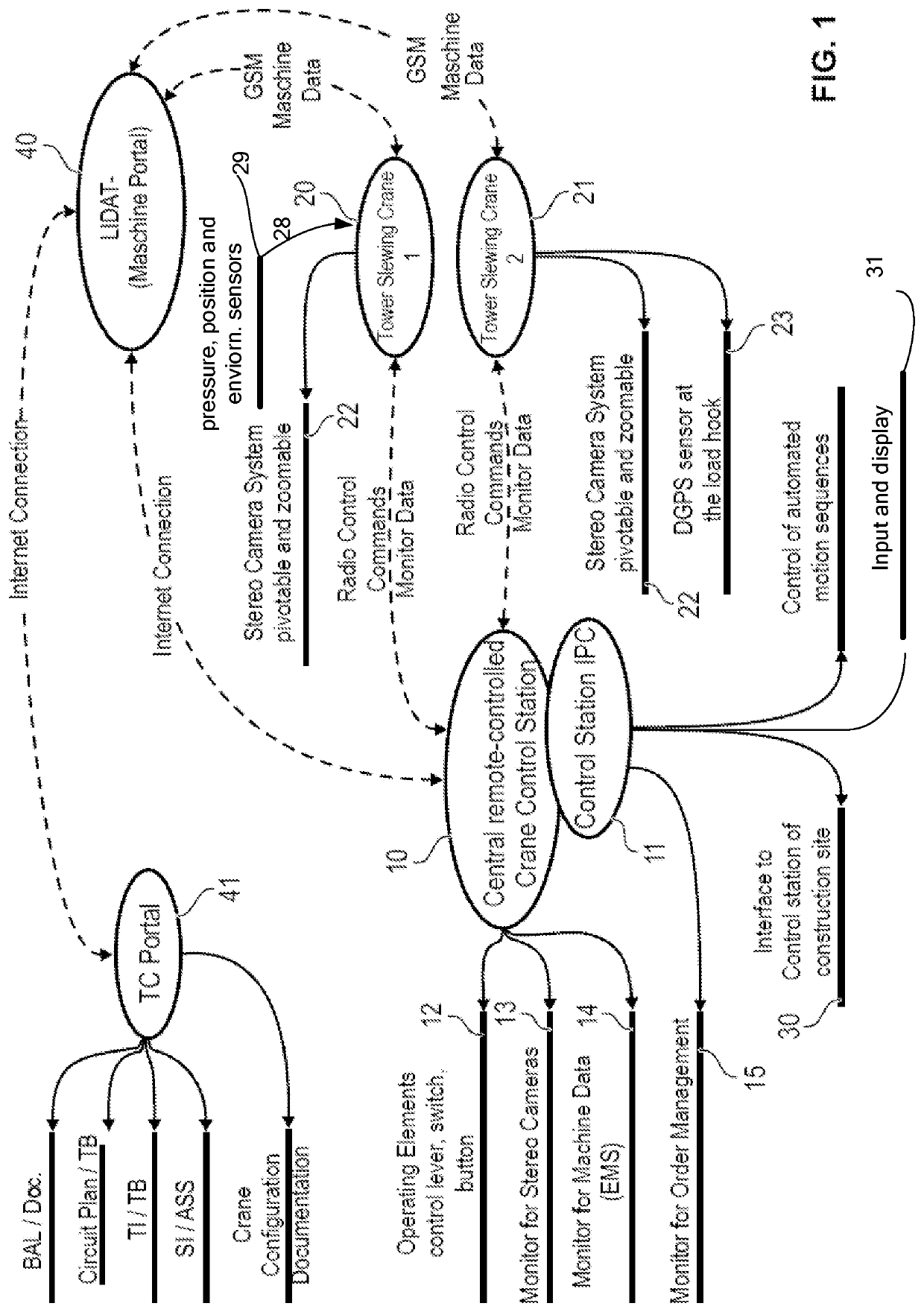
[0033]As a central element, a central remote-controlled crane control station 10 is employed, the core component of which is constituted by an industrial personal computer (IPC) 11. In its crane functions, the discrete control station 10 is nearly identical to the control station in the crane cab of a crane 20, 21 to be controlled (tower slewing crane).

[0034]The central control station 10 can be accommodated in an office container at the construction site and serves to remotely control at least one crane 20, 21. The construction of the control station 10 is composed of multiple operating elements 12, such as a control lever, switches and buttons, a 3D-capable monitor 13 for the image crane monitoring, a monitor 14 for the representation of the machine data and a monitor 14 for the monitoring of tasks.

[0035]The crane 20, 21 provides a stereo camera system 22, the individual cameras of which are pivotably mounted on the crane structure. In addition, zooming is possible by use of the c...


PUM


Abstract

The invention relates to a system for central control of one or more cranes including at least one crane and at least one central control station, wherein the crane includes one or multiple image sensors observing a picked-up load, at least part of the crane surroundings and at least part of the crane structure, the crane is connected with the control station for the transmission of the image sensor data via at least one bidirectional communication link, and wherein the control station comprises at least one display element for the visual representation of the received sensor data as well as provides at least one input device for inputting control commands, and the control commands can be transmitted, via the communication link, to one or more crane actuators and / or the crane control for performing crane movements.

Description

CROSS-REFERENCE TO RELATED APPLICATIONS[0001]The present application is a continuation of U.S. patent application Ser. No. 16 / 065,094, entitled “METHOD FOR CRANE ASSEMBLY”, and filed on Jun. 21, 2018. U.S. patent application Ser. No. 16 / 065,094 is a U.S. National Phase of International Application No. PCT / EP2016 / 002180, filed on Dec. 23, 2016. International Patent Application No. PCT / EP2016 / 002180 claims priority to German Patent Application No. 10 2015 016 848.7, filed on Dec. 23, 2015. The entire contents of each of the abovementioned applications are hereby incorporated by reference in their entirety for all purposes.TECHNICAL FIELD[0002]The invention relates to a system for central control of one or more cranes.BACKGROUND AND SUMMARY[0003]At present, tower slewing cranes are operated via a radio remote control or a control station of the crane cab mounted on the crane. The radio remote control is a remote control worn by the crane operator situated on the ground. In order to rem...

Claims


Application Information

Patent Timeline
Patent Type & Authority Applications(United States)
IPC IPC(8): B66C13/46B66C13/40B66C13/44
CPCB66C13/46B66C2700/08B66C13/44B66C13/40
Inventor SCHILLING, HERMANNHOFMEISTER, MARKUS
Owner LIEBHERR WERK BIBERACH
Why Eureka
Try Eureka