Method of visualizing a dynamic anatomical structure

a dynamic anatomical and structure technology, applied in image analysis, instruments, image enhancement, etc., can solve the problems of not being suited for all pathologies, omnipresent risk of misinterpretation of relative spatial relationships between anatomical structures represented on medical 3d, and user no longer critically questioning or verifying the volume-rendered representation of anatomy, so as to minimize the risk of image data misinterpretation

Pending Publication Date: 2022-04-28
KONINKLJIJKE PHILIPS NV
View PDF0 Cites 2 Cited by
  • Summary
  • Abstract
  • Description
  • Claims
  • Application Information

AI Technical Summary

Benefits of technology

[0013]It is therefore an object of the invention to provide a method of visualising a dynamical anatomical structure, which minimises the risk of misinterpretation the image data, and in particular the risk of misinterpreting or incorrectly measuring the relative spatial relationship between anatomical features.SUMMARY OF THE INVENTION
[0014]To better address one or more of the above-identified concerns, according to a first aspect of the invention there is provided a method of visualising a dynamic anatomical structure. The method comprises the steps ofa) providing a sequence of three-dimensional medical images spanning a time period, each three-dimensional medical image of the sequence showing a dynamic anatomical structure at a point in time during the time period;b) providing a dynamic model of at least a part of the anatomical structure, wherein the dynamic model has been derived from and is registered with the sequence of three-dimensional medical images;c) determining a volume of interest containing an anatomical feature of interest within each of the three-dimensional images, wherein the volume of interest follows the position and / or the shape of the anatomical feature of interest across the time period, and wherein the volume of interest is smaller than the complete field of view of the three-dimensional medical images; andd) providing a three-dimensional visualisation environment for displaying the dynamic anatomical structure across the time period, wherein a visualisation corresponding to a particular point in time within the time period comprises(i) a volume rendering of the volume of interest of the three-dimensional image corresponding to the particular point in time; and(ii) a visualisation of the dynamic model at the particular point in time and in the same coordinate system as the volume rendering of the volume of interest.Preferably, the three-dimensional visualisation environment allows for displaying the dynamic model and the volume rendered volume of interest for each three-dimensional image across the time period in “cine mode”, i.e. in “cinematic mode” or animation, which means that a sequence of visualisations is shown dynamically, at a frame rate of e.g. 5-100 visualisations per second.Accordingly, the invention combines two important approaches when looking at medical 3D volume data: The first approach is a dynamic, computer-generated model of at least a part of an anatomical structure. Such models have the advantages that they show a simpler version / abstraction of the anatomy, make it easier to navigate and interpret the anatomy, are not very much dependent on the image quality, and they have no “holes”, i.e. no incorporation of artefacts etc.The second approach is volume rendering, which has the advantage that it is suitable for more complex / unusual anatomies or highly individual structures like valve leaflet cusps, stenosis, calcifications, bio-prostheses, ruptured chordae etc., which cannot be modelled by software like 4D MV by TOMTEC. Further, parameters like threshold, opacity, contrast can be adjusted “live”, i.e. with immediate effect while watching a dynamic sequence of volume renderings. On the other hand, volume rendering is strongly dependent on the image quality and thus might be too complex for an easy interpretation
[0015]The invention provides a combination offering the advantages of both approaches: Volume renderings is used only for those parts of the anatomy where it is really useful and necessary. The Region in which volume rendering is used (=VOI), can be minimized to the actual feature of interest, resulting in a better overview, without the feature of interest (e.g. valve) moving out of the focus. This may be done by using points of the dynamic model to adjust the position of the VOI also dynamically.Accordingly, the invention provides an excellent overview and navigation opportunities offered by the dynamic model, e.g. a shape / surface model, in combination with the adjustable and highly individual benefits offered by volume rendering, while the volume rendering is only used where it is necessary.

Problems solved by technology

Therefore, there is an omnipresent risk to misinterpret the relative spatial relationships between anatomical structures represented on medical 3D data, when 3D data sets are viewed and analysed in orthogonal planes on 2D screens.
A frequent source of error is the selection of an incorrectly placed or twisted measuring plane for analysing and taking measurements of an anatomical structure.
It often incorporates image errors and therefore carries the risk that the user no longer critically questions or verifies the volume-rendered representation of the anatomy.
However, they are not suited for all pathologies, since complex and fine structures are not captured and displayed properly.
Accordingly, current approaches to segment and display medical image data of complex anatomical structures, for example cardiac 3D volume data, either simplify the anatomical characteristics too much by using surface or shape models, or use a threshold-based segmentation which can lead to false conclusions.
Therefore, important geometrical correlations and information, which are necessary for example when planning heart interventions, might get lost or overlooked.
However, the 3D printing process takes a lot of time and expertise, is expensive, cannot be included into daily clinical routine, and dynamic movements of anatomical structures (especially for 3D Echo) cannot be represented.

Method used


Image

  • Method of visualizing a dynamic anatomical structure
  • Method of visualizing a dynamic anatomical structure
  • Method of visualizing a dynamic anatomical structure

Examples


Embodiment Construction

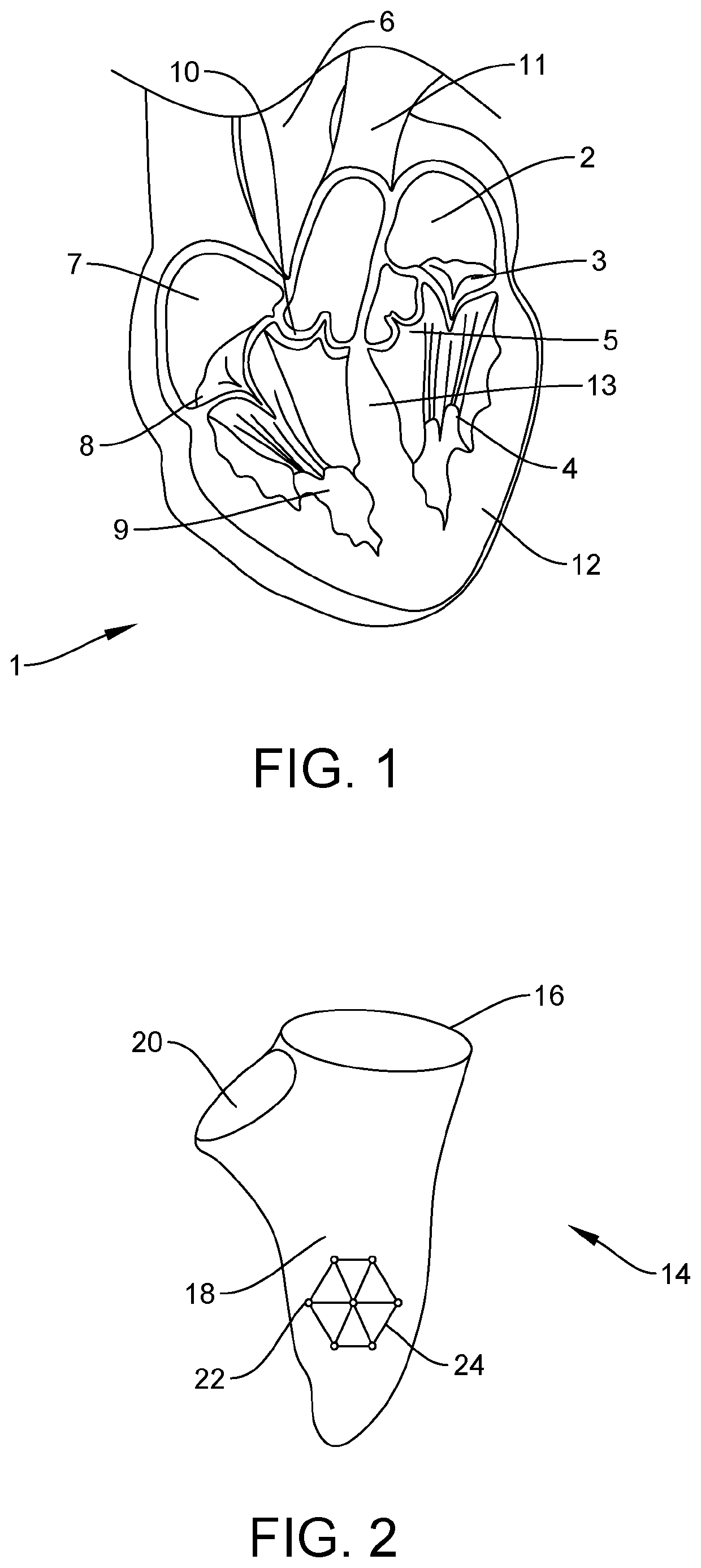
[0077]In order to better visualise the preferred application of inventive visualisation method and user interface, FIG. 1 illustrates the structure of the human heart 1. The blood coming from the lungs flows into the left atrium 2 and from there through the mitral valve 3 into the left ventricle 4. From there, it is pumped through the aortic valve 5 into the aorta 6. This part is also termed left ventricular outflow tract (LVOT). The blood coming from the body flows into the right atrium 7 and is pumped through the tricuspid valve 8 into the right ventricle 9. From there, it is pumped through the pulmonary valve 10 into the pulmonary artery 11. Heart wall 12 is made of muscular tissue surrounding the heart chambers 2, 4, 7 and 9. The left and right ventricles are separated by the septum 13. It is evident from FIG. 1 that the heart has a complex shape, and in addition is constantly moving with the heartbeat, i.e. it is a dynamic anatomical structure. Thus, a visualisation of shapes s...


PUM


Abstract

The invention relates to a method of visualising a dynamic anatomical structure (1), a computer program and a user interface. The method comprises (a) providing a sequence of three-dimensional medical images (M1, M2, M3, . . . MZ) of a dynamic anatomical structure (1) spanning a time period (T), (b) providing a dynamic model (14), in particular surface of the anatomical structure, (c) determining a volume of interest (40) containing an anatomical feature of interest (3) within each of the three-dimensional images, wherein the volume of interest (40) follows the position and / or the shape of the anatomical feature of interest (3) across the time period and wherein the volume of interest (40) is smaller than the complete field of view of the three-dimensional medical images (M1, M2, M3, . . . MZ), and (d) providing a three-dimensional visualisation environment (50, 70), wherein a visualisation (45) corresponding to a particular point in time comprises (i) a volume rendering of the volume of interest (40) of the three-dimensional image; and (ii) a visualisation of the dynamic model (14) in the same coordinate system. Preferably, the three-dimensional visualisation environment (50, 70) allows for displaying the dynamic model (14) and the volume rendered volume of interest (40) for each three-dimensional image across the time period in cine mode.

Description

FIELD OF THE INVENTION[0001]The present invention relates to a method of visualising a dynamic anatomical structure, to a related computer program and a user interface.BACKGROUND OF THE INVENTION[0002]Medical imaging techniques provide three-dimensional (3D) image data of the human or animal body. However, the images are usually viewed on two-dimensional (2D) screens. Therefore, there is an omnipresent risk to misinterpret the relative spatial relationships between anatomical structures represented on medical 3D data, when 3D data sets are viewed and analysed in orthogonal planes on 2D screens. A frequent source of error is the selection of an incorrectly placed or twisted measuring plane for analysing and taking measurements of an anatomical structure.[0003]3D volume rendering is a set of techniques used to display a 2D projection of a 3D image data set. However, although 3D volume rendering is helpful in forming a mental 3D model of the anatomy, it is strongly dependent on the ima...

Claims


Application Information

Patent Timeline
Patent Type & Authority Applications(United States)
IPC IPC(8): G06T7/00G06T7/11G06T15/08G06T19/00G06V10/25G06V10/62
CPCG06T7/0016G06T7/11G06T15/08G06T19/006G06V2201/031G06V10/62G06T2207/10076G06T2207/10016G06T2207/30048G06V10/25G06T7/246G06T19/00G06T2210/41
Inventor SCHRECKENBERG, MARCUSHITSCHRICH, NIKLAS
Owner KONINKLJIJKE PHILIPS NV
Why Eureka
Try Eureka