Systems and methods for optimizing scheduling of health checks for wind turbines during periods of low wind speeds

a technology of health check and wind turbine, applied in the field of wind turbines, can solve the problems of high probability of higher annual energy production loss, affecting the availability of wind turbines for customers, and cumulative downtime due to each test in a year can be significant, so as to improve the power production of wind turbines

Inactive Publication Date: 2021-04-22
GENERAL ELECTRIC CO
View PDF1 Cites 0 Cited by
  • Summary
  • Abstract
  • Description
  • Claims
  • Application Information

AI Technical Summary

Benefits of technology

[0009]In one aspect, the present disclosure is directed to a method for improving power production of a wind turbine. The method includes obtaining, by a controller having one or more processors, wind forecast data of the wind turbine. The method also includes scheduling, by the controller, one or more health checks for one or more components of the wind turbine based, at least in part, on the wind forecast data. Moreover, the method includes implementing, via the controller, the one or more health checks based on the scheduling such that the one or more health checks are implemented during time periods having wind speeds below a predetermined threshold.

Problems solved by technology

Although each test may vary between about 8 and 45 minutes in duration, the cumulative downtime due to each test in a year can be significant.
Thus, such tests impact the availability of the wind turbine for the customers.
In addition, since these tests are conducted as a function of time, there is high probability of higher annual energy production (AEP) loss due to the tests being conducted during higher wind speed conditions.
In addition to negatively impacting AEP, current processes for scheduling of the tests increase the effort of tracking the time passed for each test per wind turbine and then re-scheduling the test.

Method used


Image

  • Systems and methods for optimizing scheduling of health checks for wind turbines during periods of low wind speeds
  • Systems and methods for optimizing scheduling of health checks for wind turbines during periods of low wind speeds
  • Systems and methods for optimizing scheduling of health checks for wind turbines during periods of low wind speeds

Examples


Embodiment Construction

[0029]Reference now will be made in detail to embodiments of the invention, one or more examples of which are illustrated in the drawings. Each example is provided by way of explanation of the invention, not limitation of the invention. In fact, it will be apparent to those skilled in the art that various modifications and variations can be made in the present invention without departing from the scope or spirit of the invention. For instance, features illustrated or described as part of one embodiment can be used with another embodiment to yield a still further embodiment. Thus, it is intended that the present invention covers such modifications and variations as come within the scope of the appended claims and their equivalents.

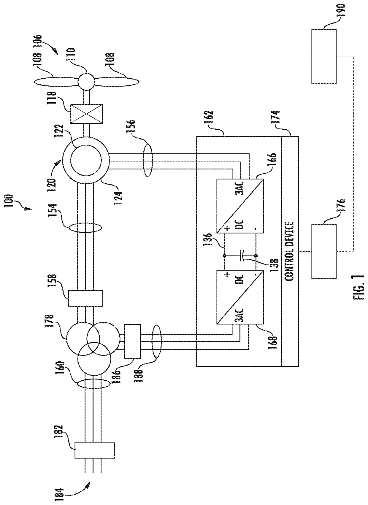
[0030]Referring now to the drawings, FIG. 1 illustrates one embodiment of a wind turbine system 100 according to the present disclosure. Example aspects of the present disclosure are discussed with reference to the wind turbine system 100 of FIG. 1 for purp...


PUM


Abstract

A method for improving power production of a wind turbine includes obtaining, by a controller having one or more processors, wind forecast data of the wind turbine. The method also includes scheduling, by the controller, one or more health checks for one or more components of the wind turbine based, at least in part, on the wind forecast data. Moreover, the method includes implementing, via the controller, the one or more health checks based on the scheduling such that the one or more health checks are implemented during time periods having wind speeds below a predetermined threshold.

Description

FIELD[0001]The present disclosure relates generally to wind turbines, and more particularly, to systems and methods for optimizing scheduling of technical standby tests / health checks such that the tests occur during periods of low wind speeds so as to minimize energy loss.BACKGROUND[0002]Wind power is considered one of the cleanest, most environmentally friendly energy sources presently available, and wind turbines have gained increased attention in this regard. A modern wind turbine typically includes a tower, generator, gearbox, nacelle, and one or more rotor blades. The rotor blades capture kinetic energy of wind using known airfoil principles. For example, rotor blades typically have the cross-sectional profile of an airfoil such that, during operation, air flows over the blade producing a pressure difference between the sides. Consequently, a lift force, which is directed from a pressure side towards a suction side, acts on the blade. The lift force generates torque on the main...

Claims


Application Information

Patent Timeline
Patent Type & Authority Applications(United States)
IPC IPC(8): F03D7/04F03D17/00
CPCF03D7/048F03D17/00F05B2270/1033F05B2270/335F05B2270/32F05B2270/321G05B23/0283G05B2219/2619F05B2260/82F03D80/50Y02E10/72
Inventor MAZUMDAR, ABHIJEETAPPURAJ, KARTHIKEYANBERTRAND, SEBASTIEN DAVID
Owner GENERAL ELECTRIC CO
Why Eureka
Try Eureka