Braking control device

a technology of braking control and control device, which is applied in the direction of braking system, vehicle sub-unit features, braking components, etc., can solve the problem of not being able to use a vehicle configured, and achieve the effect of increasing the braking force, reducing or eliminating the tendency of locking, and increasing the rotational speed of the wheel

Active Publication Date: 2021-04-29
TOYOTA JIDOSHA KK
View PDF0 Cites 3 Cited by
  • Summary
  • Abstract
  • Description
  • Claims
  • Application Information

AI Technical Summary

Benefits of technology

[0006]The present disclosure provides a braking device that, for a vehicle in which a braking force generator that generates negative torque for braking is connected to at least two wheels via the differential mechanism, brakes the wheels using the negative torque generated by the braking force generator and can preferably control the slip ratio of the wheels while changing the negative torque, which can achieve reduction of a braking distance.
[0007]An aspect of the present disclosure provides a braking control device of a vehicle in which a braking force generator that generates a braking force that acts in a direction to reduce a rotation of a plurality of wheels is connected to a differential mechanism to which the plurality of wheels is connected, and a friction brake that generates a braking force that acts in a direction to stop the rotation of the wheels through friction is provided for each of the wheels. The braking control device includes a controller configured to control the braking force that is generated by the braking force generator and the braking force that is generated by the friction brake. The controller is configured to detect the wheel having a tendency of locking in which a slip ratio is larger than a predetermined determination value in a state where the braking force is transmitted to each of the wheels from the braking force generator via the differential mechanism, and reduce the tendency of locking by changing the braking force of the friction brake that is provided for the other wheel connected to the differential mechanism to which the wheel having the tendency of locking is connected.
[0014]According to the above aspect, when a braking request is made, the braking force generator that is connected to the wheels via the differential mechanism generates the braking force, or in addition to this, the friction brake that is provided for each wheel generates the braking force. The braking force as the entire vehicle in the case above is controlled by changing the braking force generated by the braking force generator in accordance with the rotational speed and the slip ratio of the wheels. When the rotational speed (wheel speed) of any one of the wheels decreases due to a decrease of the friction coefficient of the road surface, that is, when the wheel has the tendency of locking, the braking force generated by the braking force generator mechanism does not act on the other wheel that is connected to the differential mechanism to which the wheel having the tendency of locking is connected due to the differential action of the differential mechanism. When the tendency of locking is detected, the braking force of the friction brake provided for the other wheel is changed (more specifically, the braking force is increased). As a result, the braking force that is generated by the braking force generator and acts on the wheel having the slip ratio that increases, which reduces or eliminates the tendency of locking. The braking force by the friction brake may be controlled such that the rotational speed of the other wheel matches the target wheel rotational speed. That is, when any of the wheels has the tendency of locking, the braking control device of the present disclosure applies braking to the wheel other than the wheel having the tendency of locking using the frictional brake. As a result, a state similar to the state where differential limitation is imposed on the differential mechanism arises and the braking force that is generated by the braking force generator and is applied to the wheel of which tendency of locking is determined is reduced, which increases the rotational speed of the wheel. That is, the tendency of locking is corrected. In addition, the entire braking force of the other wheel increases, the rotational speed of the other wheel is controlled to match the target wheel rotational speed, and the friction coefficient of the other wheel approaches the maximum value. As a result, the wheel speed or the slip ratio of each wheel connected to the differential mechanism is controlled such that the friction coefficient increases. Therefore, the braking performance of the entire vehicle is improved. In other words, the braking distance can be shortened.

Problems solved by technology

Therefore, the braking device described in JP 2014-079099 A cannot be used for a vehicle configured such that regenerative braking is performed via the differential mechanism.

Method used


Image

  • Braking control device
  • Braking control device
  • Braking control device

Examples


Embodiment Construction

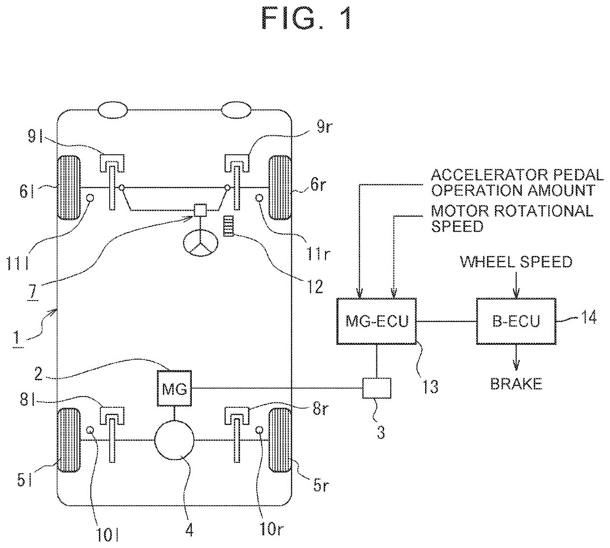
[0024]A vehicle according to an embodiment of the present disclosure can recover (regenerate) a kinetic energy by converting the kinetic energy into an electric power, etc., and can cause torque when regenerating the energy to act on wheels as a braking force. In particular, in the vehicle, a motor or a motor-generator (hereinafter collectively referred to as a “motor”) is connected to a differential gear (differential mechanism), and right and left wheels are connected to the differential gear. Further, each wheel may be provided with a brake mechanism, such as a friction brake mechanism, that performs braking different from regenerative braking, and may be configured to perform braking of the vehicle using both of regenerative braking and friction braking.

[0025]FIG. 1 schematically shows a vehicle of this type. A vehicle 1 shown in FIG. 1 is an electric vehicle that uses a motor (MG) 2 as a driving force source. The motor 2 is, for example, a permanent magnet type synchronous moto...


PUM


Abstract

A braking control device of a vehicle in which a braking force generator is connected to a differential mechanism to which a plurality of wheels is connected, and a friction brake is provided for each of the wheels includes a controller configured to control braking forces of the braking force generator and the friction brake. The controller is configured to: detect the wheel having a tendency of locking in which a slip ratio is larger than a predetermined determination value in a state where the braking force is transmitted to each of the wheels from the braking force generator via the differential mechanism; and reduce the tendency of locking by changing the braking force of the friction brake that is provided for the other wheel connected to the differential mechanism.

Description

INCORPORATION BY REFERENCE[0001]The disclosure of Japanese Patent Application No. 2019-192471 filed on Oct. 23, 2019 including the specification, drawings and abstract is incorporated herein by reference in its entirety.BACKGROUND1. Technical Field[0002]The present disclosure relates to a braking control device that controls a braking force or a braking device that decelerates a vehicle, and in particular, relates to a braking control device that controls a braking force of wheels that are connected to each other via a differential mechanism.2. Description of Related Art[0003]A driving force source such as an engine mounted on a vehicle outputs torque by power conversion, and also generates negative torque that accompanies conversion of an external force into a pressure, a heat, and / or an electric power, when the driving force source is rotated by the external force. The state where the vehicle is braked using the negative torque is an engine brake (power source brake) state or a re...

Claims


Application Information

Patent Timeline
Patent Type & Authority Applications(United States)
IPC IPC(8): B60T8/1761B60T8/24B60T8/72B60T8/172
CPCB60T8/1761B60T8/246B60T2270/611B60T8/172B60T2250/04B60T8/72B60L15/20B60T8/175B60L15/2009B60L7/10B60T8/32B60T8/3215Y02T10/72B60T13/585B60T2270/606B60Y2400/80B60L7/00B60T8/00B60W10/00
Inventor OKUMURA, KAZUYAKUBONOYA, HIDEKISUZUKI, YUSUKE
Owner TOYOTA JIDOSHA KK
Why Eureka
Try Eureka