Monitoring system and monitoring method

Inactive Publication Date: 2021-04-29
KOKUSA ELECTRIC CO LTD
View PDF0 Cites 2 Cited by
  • Summary
  • Abstract
  • Description
  • Claims
  • Application Information

AI Technical Summary

Benefits of technology

The present invention provides a monitoring system for multiple vehicle doors of a train using multiple monitoring cameras. The system includes a controller that can acquire videos from the cameras and determine which cameras are in an abnormal state. In this case, the controller can extract videos from different cameras that are paired with the abnormal cameras to cover the monitoring target areas. The system can also adjust the angle of view and capture ranges of the cameras to include the monitoring target areas. This invention allows for real-time monitoring without downtime and reduces the burden on crew members, making it easier to cope with various operation modes.

Problems solved by technology

For this reason, the vehicle door 221 cannot be monitored in real time, which hinders the system operation.
In particular, in the case that the monitoring camera is attached to the vehicle of the train, it is difficult to perform restoration and repair work during daytime operation, which may extend the time during which the monitoring operation cannot be performed.
This visual confirmation requires the crew member to step outside of the vehicle to visually confirm the vehicle doors, which imposes a heavy burden on the crew member.
In this operation mode, however, if the camera monitoring the vehicle door breaks down, the crew member must go outside of the vehicle each time to visually confirm the vehicle door, which also increases the burden on the crew.

Method used


Image

  • Monitoring system and monitoring method
  • Monitoring system and monitoring method
  • Monitoring system and monitoring method

Examples


first embodiment

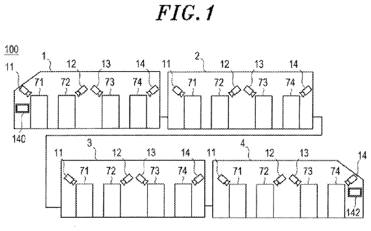
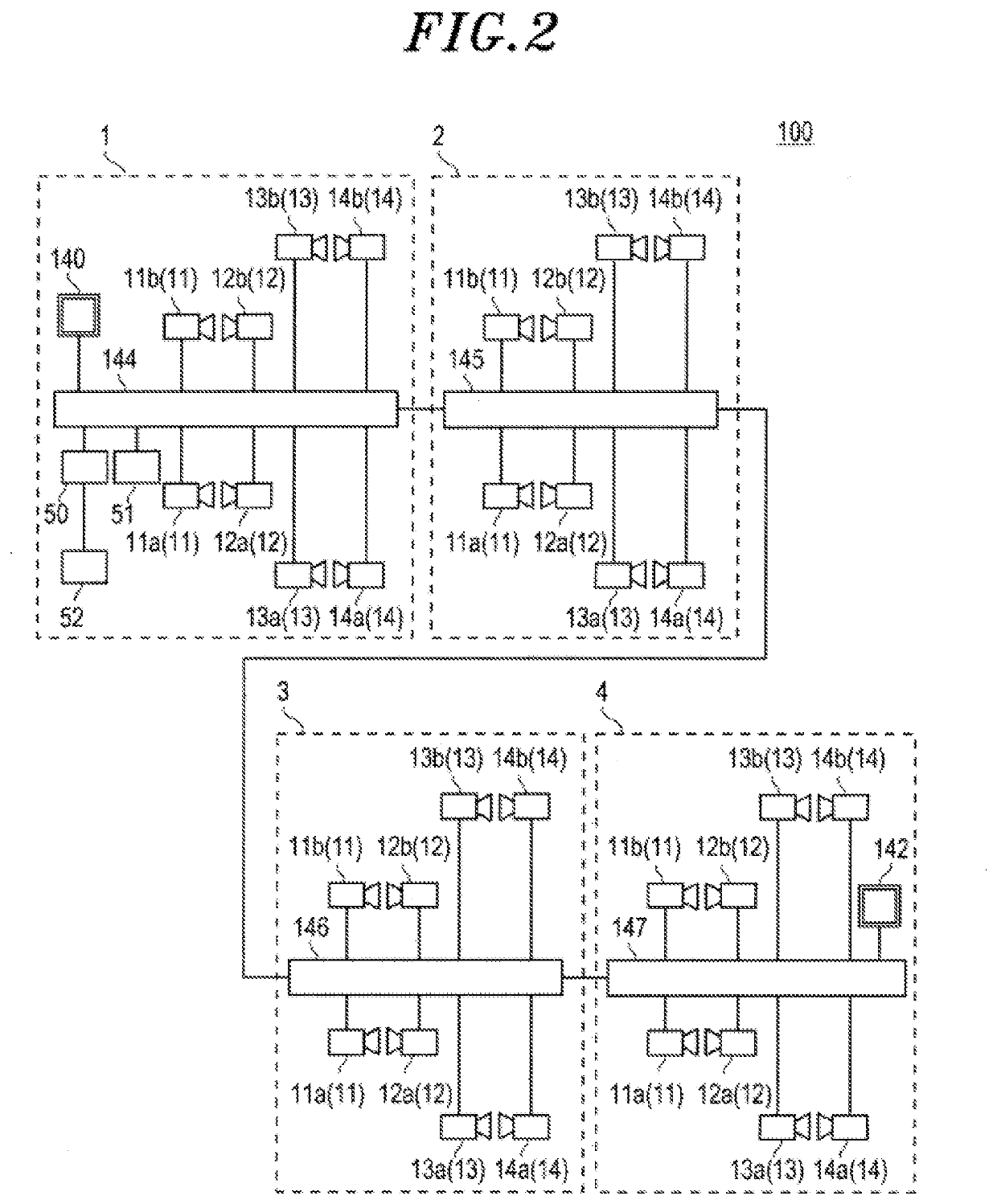
[0036]FIG. 1 schematically shows an example of a layout of a railway monitoring system 100 installed in a single train set to monitor an area around a doorway (door) from the inside of the train. FIG. 2 is a block diagram for explaining an embodiment of a configuration of the railway monitoring system 100. FIG. 1 describes mainly an installation and arrangement of the railway monitoring system 100 in the train while FIG. 2 describes mainly connections among respective components constituting the railway monitoring system 100. Frames of broken lines shown in FIG. 2 indicate a first to a fourth vehicle 1 to 4 shown in FIG. 1, respectively. All the components constituting the railway monitoring system 100 may be connected with one another by a wired connection using, e.g., a network cable.

[0037]The train shown in FIG. 1 is a four-vehicle train including a first vehicle 1 serving as a leading vehicle, a second vehicle 2 and a third vehicle 3 serving as intermediate vehicles, and a fourt...

second embodiment

[0088]A second embodiment will be described with reference to FIGS. 11 to 13. FIG. 11 schematically shows an operation mode of the second embodiment. FIG. 12 is a flowchart showing an operation of the server 50. FIG. 13 shows an operation sequence for the server 50, the first monitoring camera 11, the second monitoring camera 12, and the monitor (the divided section A 81 and the divided section B 82). The configuration of the railway monitoring system 100 of the second embodiment is the same as that of the first embodiment, so that processing operations thereof will be mainly described hereinafter.

[0089]In the second embodiment, when the first monitoring camera 11 breaks down, the angle of view of the second monitoring camera 12 is not widened. Instead, all of the monitoring cameras are set in advance such that each monitoring camera has a wide-angle view (monitoring range 30A) so as to capture an area including a door that is captured by the paired camera thereof. In other words, e...

third embodiment

[0100]In a third embodiment, for the case when the driver or the crew member sitting in a train driver room or the train control room has difficulty confirming the monitoring areas in the railway monitoring system 100, a control button is prepared on a control screen of a system software, or a control device is prepared such that the video display operation from the paired cameras can be performed even if the first to the fourth monitoring cameras 11 to 14 do not break down. For example, when the video is unclear due to, e.g., lens contamination of the first monitoring camera 11, the video from the second monitoring camera 12 is used. The process of the third embodiment may be performed together with the above-described automatic switching method performed by monitoring the state of the monitoring camera.

[0101]FIG. 14 is a flowchart showing the operation of the server 50. FIG. 15 shows an operation sequence for the server 50, the first monitoring camera 11, the second monitoring cam...


PUM


Abstract

Provided is a technology for monitoring vehicle doors of a train that achieves monitoring with substantially no downtime when any one of multiple monitoring cameras breaks down. A first to a fourth monitoring camera attached outside of a vehicle to monitor a first to a fourth door of the vehicle. A first monitoring camera and a second monitoring camera are paired with each other, and a third monitoring camera and a fourth monitoring camera are paired with each other. If the first monitoring camera breaks down, the second monitoring camera captures areas of both the first door and the second door, and trims and extracts each of the areas.

Description

TECHNICAL FIELD[0001]The present invention relates to a monitoring system and a monitoring method, and more particularly to a monitoring system and a monitoring method for doors of a railway vehicle.BACKGROUND[0002]Recently, in addition to the monitoring of the inside and outside of a railway vehicle and a station platform in a railway monitoring system, the monitoring of vehicle doors is required to confirm whether the vehicle doors are normally operated (for example, no passenger or foreign matter being stuck in the door) when a train is stopped at the station platform to open and close the vehicle doors. Various techniques for a train door monitoring device have been proposed (see, e.g., Patent Document 1).[0003]FIG. 19 shows an example of a conventional vehicle door monitoring system 200. Here, one vehicle 240 is shown as an example. FIG. 20 shows an example of a monitor screen 280 for assigning videos acquired by a first to a fourth monitoring camera 211 to 214.[0004]The first ...

Claims


Application Information

Patent Timeline
IPC IPC(8): G06K9/00
CPCG06K9/00771G06K9/00832B61L23/041B61L15/0081B61L15/0063H04N7/181G06V20/52G06V20/59
Inventor OHKI, KANA
Owner KOKUSA ELECTRIC CO LTD
Why Eureka
Try Eureka