Sensor for emitting signals and for receiving reflected echo signals, and system including a control unit and such a sensor

a technology of reflected echo signal and sensor, which is applied in the direction of instruments, data switching networks, and using reradiation, etc., can solve the problems of inability to reach, inability to transmit analog measuring signals directly by transducers, and inability to meet the needs of digital communication interface transmission, etc., to achieve high data transmission rate, and high energy demand

Active Publication Date: 2021-04-29
ROBERT BOSCH GMBH
View PDF0 Cites 0 Cited by
  • Summary
  • Abstract
  • Description
  • Claims
  • Application Information

AI Technical Summary

Benefits of technology

[0026]However, the transmission at a higher data rate causes a higher demand for energy, as well as usually a higher susceptibility to faults during the data transmission. Advantageously, in the case of the sensor of the present invention as well as the system of the present invention, the high data-transmission rate is used only when a higher transmission capacity is needed because of the increase in data volume owing to the diagnostic data.
[0027]Compared to the output of analog measured values at the communication interfaces of the sensor known from the related art, the design approach proposed has the advantage that no additional components are necessary for the evaluation. External analog-to-digital converters for acquiring analog test signals are not necessary. Advantageously, the same infrastructure in the form of the digital communication interface

Problems solved by technology

The ports are available internally in the sensor, so that in the installed state, they are no longer reachable without damaging it.
Without an analog-to digital conversion, the analog measuring signal provided directly by the transducer is not suitable for transmission v

Method used


Image

  • Sensor for emitting signals and for receiving reflected echo signals, and system including a control unit and such a sensor
  • Sensor for emitting signals and for receiving reflected echo signals, and system including a control unit and such a sensor

Examples


Embodiment Construction

[0033]In the description below of the exemplary embodiments of the present invention, identical components and elements are denoted by identical reference numerals, a repeated description of these components or elements being omitted in individual cases. The figures represent the subject matter of the present invention only schematically.

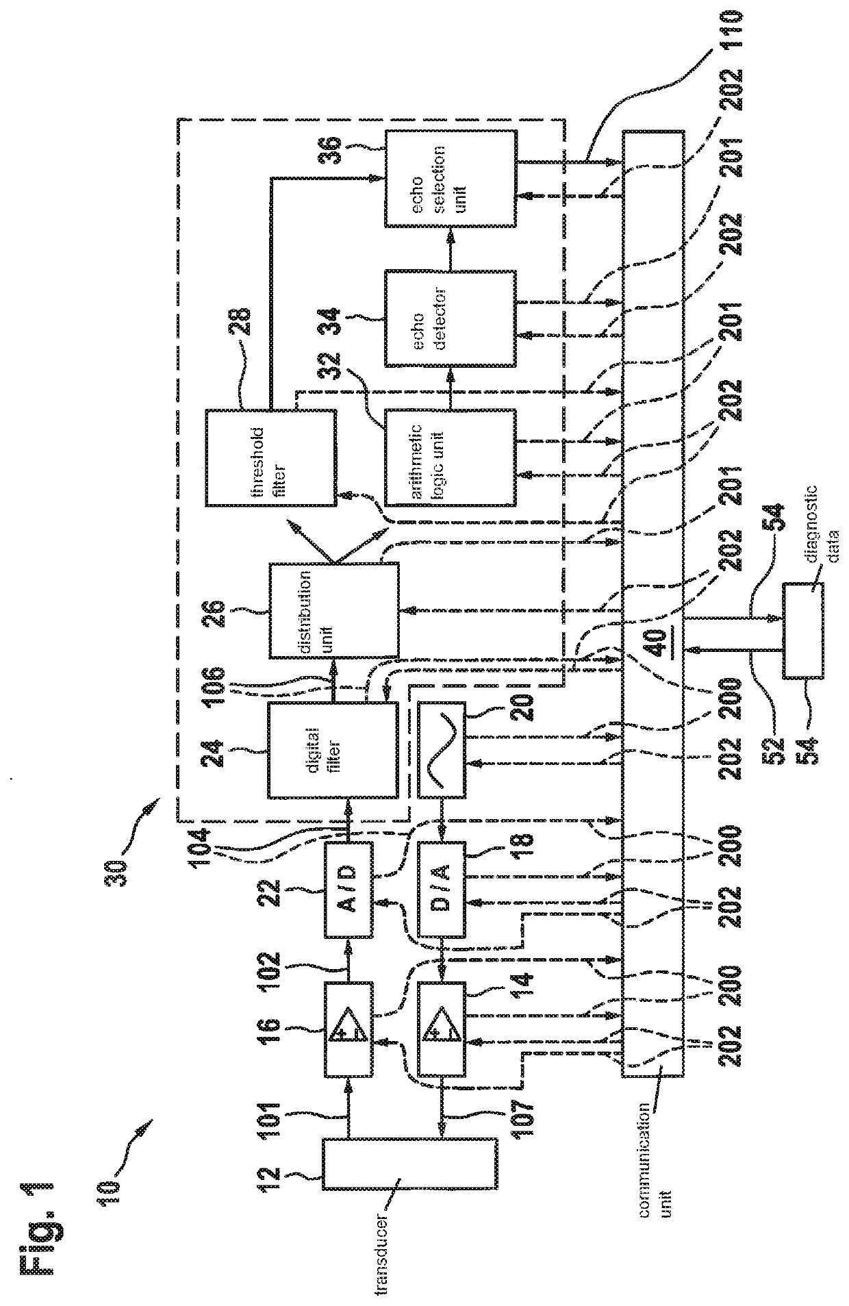
[0034]FIG. 1 shows a sensor 10 which includes a transducer 12, an evaluation unit 30 and a communication unit 40.

[0035]Transducer 12 is set up, upon receiving an analog transmit signal 107, to emit a signal. In the case of a sensor 10 in the form of an ultrasonic sensor, transducer 12 is a sound transducer, so that in response to receiving analog transmit signal 107, it emits a sound signal. In order to generate analog transmit signal 107, sensor 10 includes a signal generator 20, a digital-to-analog converter 18 as well as a transmit amplifier 14. Signal generator 20 generates a digital transmit waveform, which is passed on in digital form to digit...


PUM


Abstract

A sensor, including at least one transducer for emitting signals and for receiving reflected echo signals, the transducer being set up to output an analog measuring signal, an analog-to-digital converter for converting the analog measuring signal into a digital measuring signal, an evaluation unit for evaluating the digital measuring signal, and a communication unit for transmitting a measuring result of the evaluation via a digital communication interface. The communication unit is equipped to receive a request for diagnostic data via the digital communication interface, and is also equipped to switch the sensor to diagnostic operation and to transmit requested diagnostic data via the digital communication interface. The communication unit is set up to communicate with at least two different data rates via the digital communication interface, a higher data rate being used for transmitting the diagnostic data than for transmitting the measuring result during normal operation of the sensor.

Description

FIELD[0001]The present invention relates to a sensor including at least one transducer for emitting signals and for receiving reflected echo signals, the transducer being set up to output an analog measuring signal, an analog-to-digital converter for converting the analog measuring signal into a digital measuring signal, an evaluation unit for evaluating the digital measuring signal, and a communication unit for transmitting a result of the evaluation via a digital communication interface. A further aspect of the present invention relates to a system including a control unit and such a sensor, the control unit and the at least one sensor being connected to each other via a digital communication interface.BACKGROUND INFORMATION[0002]Modern vehicles have a multitude of sensors, via which information is obtained about the area surrounding the vehicle. To ensure reliable operation of the vehicle systems, which rely on the data obtained, it is desirable to be able to check the utilized s...

Claims


Application Information

Patent Timeline
IPC IPC(8): G07C5/08G01S7/00G01S15/931G01S7/52G08C23/04H04L12/40G01S13/931
CPCG07C5/0808G01S7/003G01S15/931G01S7/52004H04L2012/40215H04L12/40G01S13/931G01S2013/9324G08C23/04G01S7/4004G08C23/02H04Q9/00H04Q2209/30
Inventor KLOTZ, ALBRECHTSCHMID, DIRKSCHUMANN, MICHAELTREPTOW, THOMAS
Owner ROBERT BOSCH GMBH
Why Eureka
Try Eureka