
Magnetic recording tape and manufacturing method thereof, and magnetic recording tape cartridge

a manufacturing method and magnetic recording tape technology, applied in the field can solve the problems of tape during high-speed running, tape may become unstable, and prevent the off-tracking phenomenon of magnetic recording tapes, etc., to achieve stably run, suppress friction and spacing phenomena, and high speed

Active Publication Date: 2021-04-29
SONY CORP
View PDF0 Cites 28 Cited by
  • Summary
  • Abstract
  • Description
  • Claims
  • Application Information

AI Technical Summary

Benefits of technology

This technology can make magnetic recording tape run more smoothly and at high speeds by reducing friction and spacing between the tape and magnetic head. This prevents any increase in friction that can cause problems while recording and reproducing with a magnetic head.

Problems solved by technology

In recent years, owing to the wide spreading of the Internet and cloud computing, and the increasing accumulation and analysis of big data, the amount of information to be stored for long term is explosively increasing.
If the track density is made higher, prevention of the off-tracking phenomenon during high-speed running of the magnetic recording tape becomes a more important problem.
Then, the running of the tape during high-speed running may become unstable, whereby the off-tracking phenomenon may tend to occur.
Especially when high-speed running of a tape is performed for a long time or is repeated many times, the tape may be deformed due to the occurrence of an excessive distance (spacing) or increased friction between a magnetic head and the running tape.
As a consequence, no suitable state of contact of the tape to the magnetic head is available, potentially leading to deteriorating characteristics of the magnetic recording or reproduction from the tape.

Method used


Image

  • Magnetic recording tape and manufacturing method thereof, and magnetic recording tape cartridge
  • Magnetic recording tape and manufacturing method thereof, and magnetic recording tape cartridge
  • Magnetic recording tape and manufacturing method thereof, and magnetic recording tape cartridge

Examples


experiment 1

(Experiment 1)

[0225]The present inventors conducted evaluation of each magnetic recording tape primarily based on the relation between the depth and number of indentations in the magnetic layer, between the height and number of projections on the backing layer, and the like.

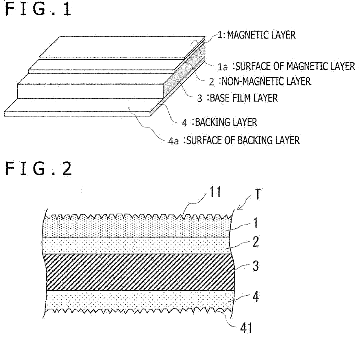
[0226]Magnetic recording tapes of Examples 1 to 14 and Comparative Examples 1 to 8 presented below in Table 1 were each produced. Adjustment of the orientation of the magnetic recording tapes was conducted as will be described hereinafter. Specifically, a PEN film that had an elongated shape and an average thickness of 4.0 μm was provided as a base film layer. A non-magnetic layer (underlayer) forming coating formulation was applied to the PEN film, followed by drying to form a non-magnetic layer having an average thickness of 1.0 to 1.1 μm on the PEN film. A magnetic layer forming coating formulation was applied to the non-magnetic layer, followed by drying to form, on the non-magnetic layer, a magnetic layer of...

experiment 2

(Experiment 2)

[0234]Using a non-contact optical interferometric roughness meter (manufactured by Ryoka Systems, Inc., product name: VertScan), a measurement experiment was next conducted about the surfaces of magnetic layers. The magnification of an object lens was set at 50 times in the measurements. Tape samples used in the measurements were those of Examples 1, 5 and 8 and Comparative Examples 6, 7 and 8 (two tape samples for different measurement locations, Comparative Examples 8-1 and 8-2).

[0235]In this Experiment 2, the surface roughness of each magnetic layer was acquired in terms of Ssk value (skewness) and Sku value (kurtosis). Ssk value is a value that represents the degree of symmetry of height distribution, and Ssk value=0 indicates that the height distribution is vertically symmetrical, Ssk value >0 indicates a surface with many fine peaks, and Ssk value 3 indicates a surface with sharp peaks and valleys, and Sku value <3 indicates a planar surface. Measurement results ...

experiment 3

(Experiment 3)

[0238]Using an atomic force microscope (abbreviation: AFM, manufactured by Degital Instruments, NanoScope Ma), the surfaces of magnetic layers were observed under magnification.

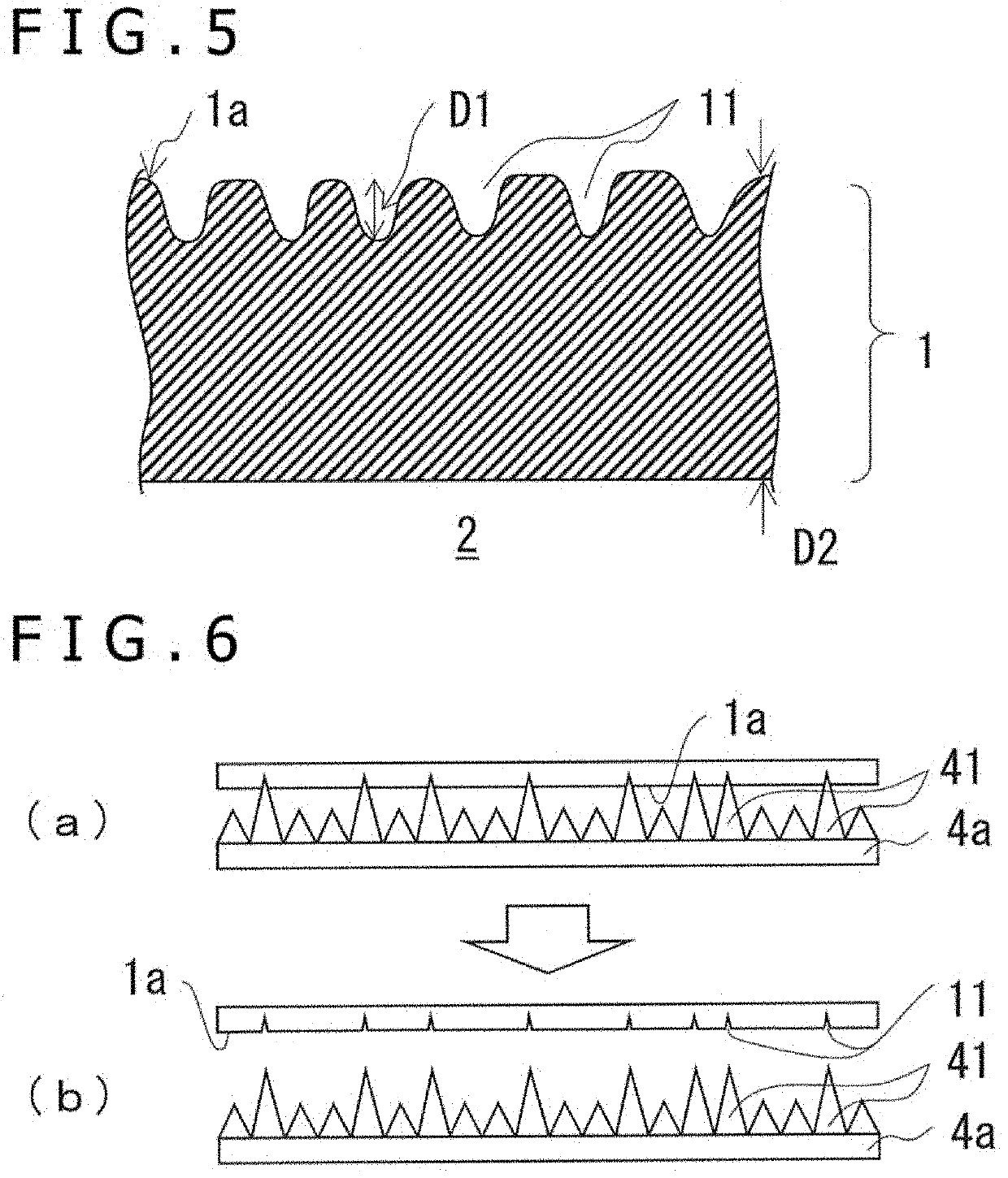
[0239]FIG. 12 presents drawing substitute photographs, in which the photograph (a) is an atomic force photomicrograph of the surface of a magnetic layer in a case where no transfer step was conducted, and the photograph (b) is an atomic force photomicrograph of the surface of another magnetic layer in a case where a transfer step was conducted. In this Experiment, the transfer step was conducted with projections formed on each backing layer from 80 mass % of small carbon particles of 20 nm average particle size and 20 mass % of large carbon particles of 270 nm average particle size.

[0240]From a comparison between these two photographs, it was successfully confirmed that even by conducting a transfer step only once, many indentations are effectively formed in the surface of a magnetic layer and t...


PUM

PropertyMeasurementUnit
thicknessaaaaaaaaaa
surface areaaaaaaaaaaa
depth D1aaaaaaaaaa

Abstract

This technology aims to provide a magnetic recording tape and the like, which allow the tape to stably run at high speed while maintaining a state in which the distance between a magnetic head and the tape is held narrow.This technology provides a magnetic recording tape having a plural-layer structure including at least a magnetic layer. The tape has a total thickness of 5.6 μm or smaller, and includes a plurality of indentations disposed in a surface of the magnetic layer. A value obtained by dividing a depth D1 of each indentation with a thickness D2 of the magnetic layer is 15% or greater. The magnetic layer is perpendicularly oriented, and has a perpendicular orientation of 65% or greater under condition of no demagnetization correction. The magnetic layer includes a plurality of indentations formed therein, a plurality of the indentations each has a depth of 20% or greater of the thickness of the magnetic layer, and the number of the indentations is 55 or more per 6,400 μm2 of a surface area of the magnetic layer. This technology also provides a manufacturing method of the magnetic recording tape.

Description

TECHNICAL FIELD[0001]This technology relates to a magnetic recording tape and the like, and more specifically to a magnetic recording tape capable of stably running relative to a magnetic head, a cartridge with the tape accommodated therein, and a manufacturing method of the tape.BACKGROUND ART[0002]In recent years, owing to the wide spreading of the Internet and cloud computing, and the increasing accumulation and analysis of big data, the amount of information to be stored for long term is explosively increasing. There is, accordingly, an outstanding demand for higher recording capacity on recording media to be used for backing up or archiving a great deal of information as data. Among such recording media, “magnetic recording tapes” (which may be abbreviated as “tapes” in certain instances) have drawn attention again from the viewpoints of cost, energy saving, long life, reliability, capacity, and so on.[0003]Such a magnetic recording tape is contained in a case with an elongated...

Claims


Application Information

Patent Timeline
Patent Type & Authority Applications(United States)
IPC IPC(8): G11B5/73G11B5/78
CPCG11B5/736G11B5/78G11B5/70678G11B5/7358G11B5/68G11B5/7356
Inventor YAMAGA, MINORUIWAMA, TAKANOBUTAKAHASHI, JUN
Owner SONY CORP
Features
  • Generate Ideas
  • Intellectual Property
  • Life Sciences
  • Materials
  • Tech Scout
  • Unparalleled Data Quality
  • Higher Quality Content
  • 60% Fewer Hallucinations
Learn More