
Transfer assembly and system for aquaculture

a technology of transfer assembly and aquaculture, which is applied in the direction of water/sewage multi-stage treatment, water/sewage treatment by degassing, separation process, etc., can solve the problems of transferring marine life between different tanks, based on their stages of development, and alarming decline in conventional fisheries, so as to facilitate the maintenance of the predetermined temperature and facilitate the disposition of the path

Active Publication Date: 2021-05-06
ATLANTIC SAPPHIRE IP L L C
View PDF20 Cites 6 Cited by
  • Summary
  • Abstract
  • Description
  • Claims
  • Application Information

AI Technical Summary

Benefits of technology

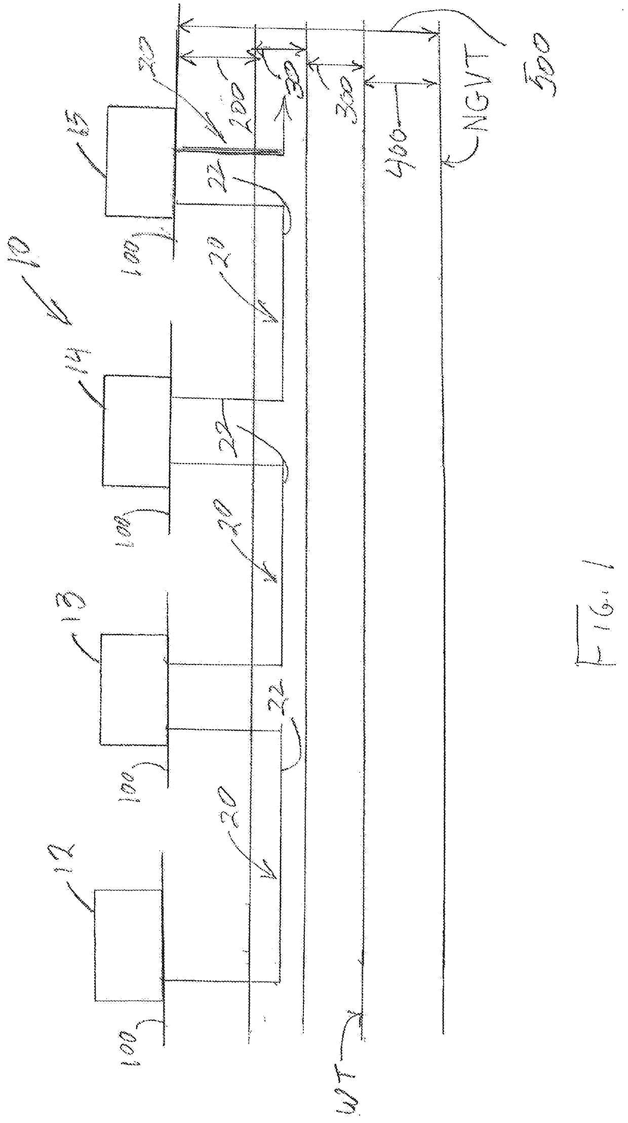
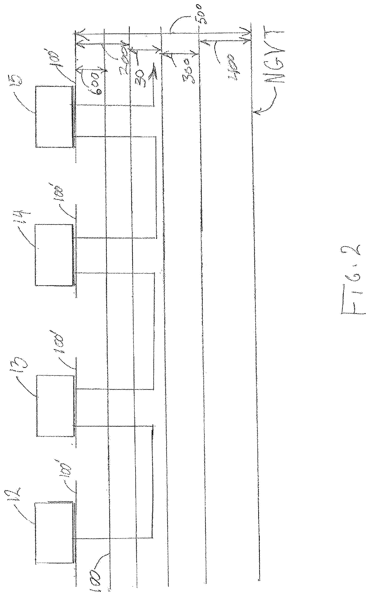
The patent is about a way to maintain the temperature of a fluid flow path in an underground storage facility. To do this, the patent suggests placing the fluid flow path at a specific depth and a certain distance from the surrounding water table or aquifer. This distance should be at least a certain amount to prevent heat transfer from the water table to the fluid flow path. Additionally, the patent describes raising the ground levels where the storage facilities are located to create a space between the fluid flow path and the existing ground level. This space should be at least as tall as the fluid flow path is from the bottom to the top, to allow for the proper maintenance of the fluid flow path's temperature.

Problems solved by technology

Currently, there is a recognized alarming decline in conventional fisheries, which in turn is based on overfishing and harmful environmental happenings.
Accordingly, the inability of conventional fisheries to meet such an increasing demand for seafood has resulted in an equally increasing need for aquaculture systems or “fish farms” capable of significantly high volume of seafood production.
In turn, this may have a derogatory effect on the environment in the form of pollution of coastal areas.
Therefore, in terms of maintaining effective environmental standards, the transferring of the marine life between the different tanks, based on their stages of development may be problematic.

Method used


Image

  • Transfer assembly and system for aquaculture
  • Transfer assembly and system for aquaculture

Examples


Embodiment Construction

[0034]As schematically represented in the accompanying Figures, the present invention is generally represented as 10 and is directed to the transferring of marine life within an aquaculture system, between a plurality of storage facilities 12, 13, 14, 15, etc. based, at least in part, on a stage of growth and / or development of the marine life while being processed. For purposes of clarity, the storage facilities 12-15, etc. each include structures such as, but not limited to, tanks maintaining containment water for the marine life which are adequate in number and dimension to process the marine life during a particular stage of growth and / or development. Also, as used herein the term aquaculture system is meant to include, but not be limited to, a recirculating aquaculture system (RAS).

[0035]Further, in the different embodiments of FIGS. 1 and 2 each of the storage facilities 12-15, etc. may include a single tank or like containment structure or a plurality of such tanks or containm...


PUM

PropertyMeasurementUnit
Temperatureaaaaaaaaaa
Volumeaaaaaaaaaa
Depthaaaaaaaaaa

Abstract

A system for transferring marine life within an aquaculture facility including a plurality of segregated storage facilities each containing water for marine life, maintained within a predetermined temperature range and supported at independent ground levels. The storage facilities are successively disposed and structured to contain marine life at different stages of growth. A transfer assembly includes a path of fluid flow interconnecting successive ones of said plurality of storage facilities in fluid communication with one another, wherein at least a majority of a length of said path of fluid flow is disposed beneath the independent ground levels at a predetermined depth, which is sufficient to facilitate maintenance of the path of fluid flow within the predetermined temperature range, via geothermal cooling.

Description

CLAIM OF PRIORITY[0001]This application is a Continuation-in-Part of U.S. Patent having Ser. No. 16 / 916,986, which was filed on Jun. 30, 2020, which is a Continuation-in-Part of U.S. Patent having Ser. No. 15 / 867,100 which was filed on Jan. 10, 2018, which matured into U.S. Pat. No. 10,034,461 and issued on Jul. 31, 2018, which was a Continuation of U.S. Patent having Ser. No. 15 / 157,296 which was filed on May 17, 2016, which matured into U.S. Pat. No. 10,694,722 and issued on Jun. 30, 2020, which claims benefit to Provisional Application having Ser. No. 62 / 165,144 filed on May 21, 2015. Finally, this application also claims priority to U.S. Provisional Patent Application having Ser. No. 62 / 975,410, filed on Feb. 12, 2020. Each of the above applications are incorporated by reference herein in their entirety.BACKGROUND OF THE INVENTIONField of the Invention[0002]The present invention is directed to a transfer assembly and system associated with an aquaculture system operative for the...

Claims


Application Information

Patent Timeline
IPC IPC(8): A01K63/04A01K63/00B01D21/24B01D21/01C02F9/00C02F1/32C02F3/30
CPCA01K63/045C02F2101/16A01K63/047A01K63/006B01D21/2455B01D21/01C02F9/00C02F1/325C02F3/305A01K63/04C02F2209/03C02F2209/42C02F2209/05C02F2209/22C02F2209/02A01K63/042A01K63/00C02F1/004C02F1/20C02F1/32C02F1/66C02F3/04C02F3/08C02F11/123C02F11/143C02F2101/105C02F2209/005C02F2209/06C02F2209/40C02F2303/16Y02W10/10C02F2303/04C02F2103/20C02F3/085C02F1/001C02F11/14C02F2301/046
Inventor HOLM, THUE
Owner ATLANTIC SAPPHIRE IP L L C
Learn More