Optical Fiber Sensing Device for Sensing the Distribution of the Compression or Deformation of a Compressible or Deformable Element

a technology of optical fiber and compression or deformation, which is applied in the direction of measurement devices, instruments, and conversion of sensor output, etc., can solve the problems of inability to accurately measure the amount of compressive force being exerted on the optical fiber (cable), and the inability to verify the direction of compressive force being exerted on the optical fiber. achieve the effect of accurate determination

Active Publication Date: 2021-05-06
COMPASS EURO GRP CEG BV
View PDF0 Cites 0 Cited by
  • Summary
  • Abstract
  • Description
  • Claims
  • Application Information

AI Technical Summary

Benefits of technology

[0007]An object of the invention is therefore to provide an optical fiber sensing device for sensing the distribution of the amount of compression or deformation of a compressible or deformable element, wherein the amount of compression or deformation of the compressible or deformable element can be accurately determined from the change in the light passing through or reflected from the light distortion element in the optical fiber.

Problems solved by technology

A problem with the known optical fiber sensing devices, however, is that it is very difficult to accurately measure the amount of compressive force being exerted on the optical fiber (cable).
A further problem with the known optical fiber sensing devices is that it is next to impossible to verify the direction of the compressive forces being exerted on the optical fiber.
However, such information is highly critical for predicting the integrity and possible failure of the compressible or deformable element, in particular when the compressible or deformable element is a gasket.

Method used


Image

  • Optical Fiber Sensing Device for Sensing the Distribution of the Compression or Deformation of a Compressible or Deformable Element
  • Optical Fiber Sensing Device for Sensing the Distribution of the Compression or Deformation of a Compressible or Deformable Element
  • Optical Fiber Sensing Device for Sensing the Distribution of the Compression or Deformation of a Compressible or Deformable Element

Examples


Embodiment Construction

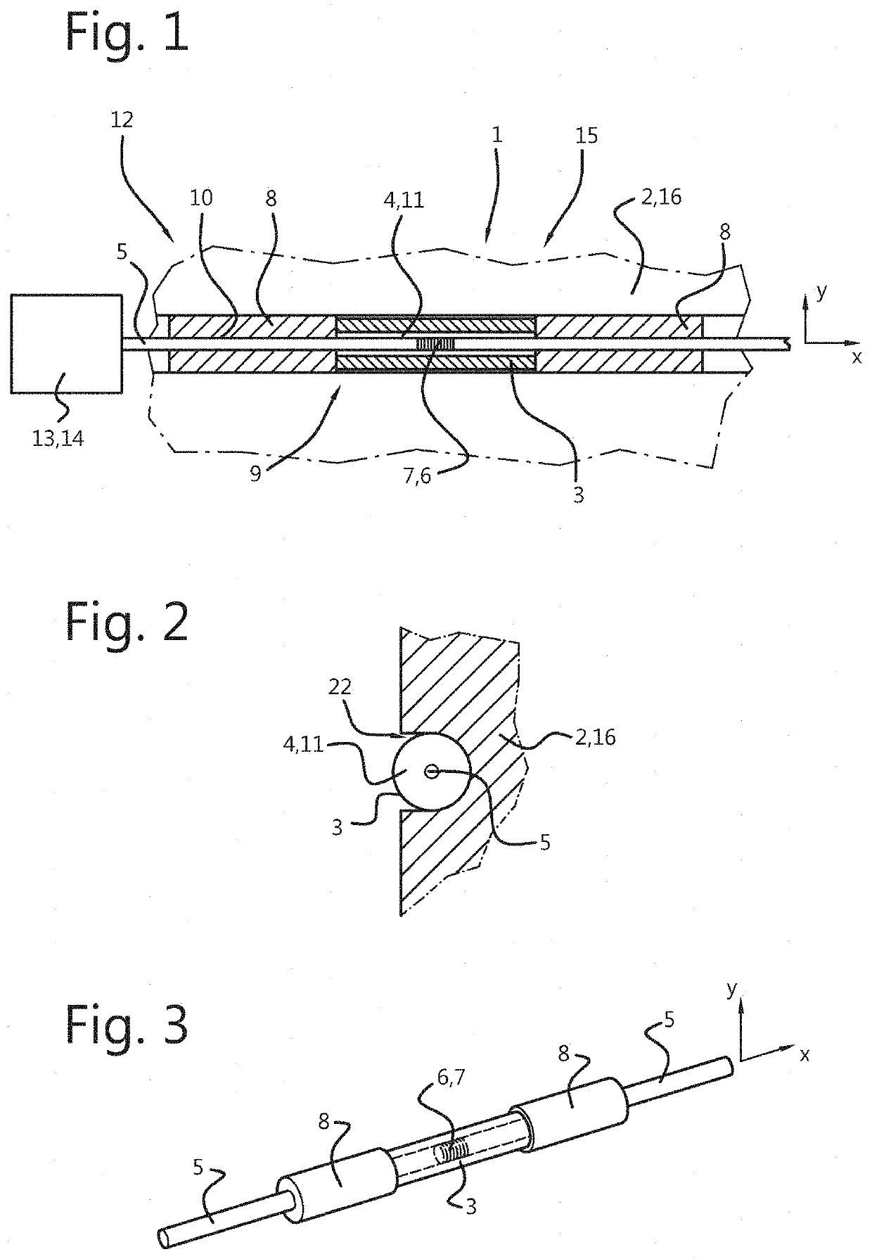
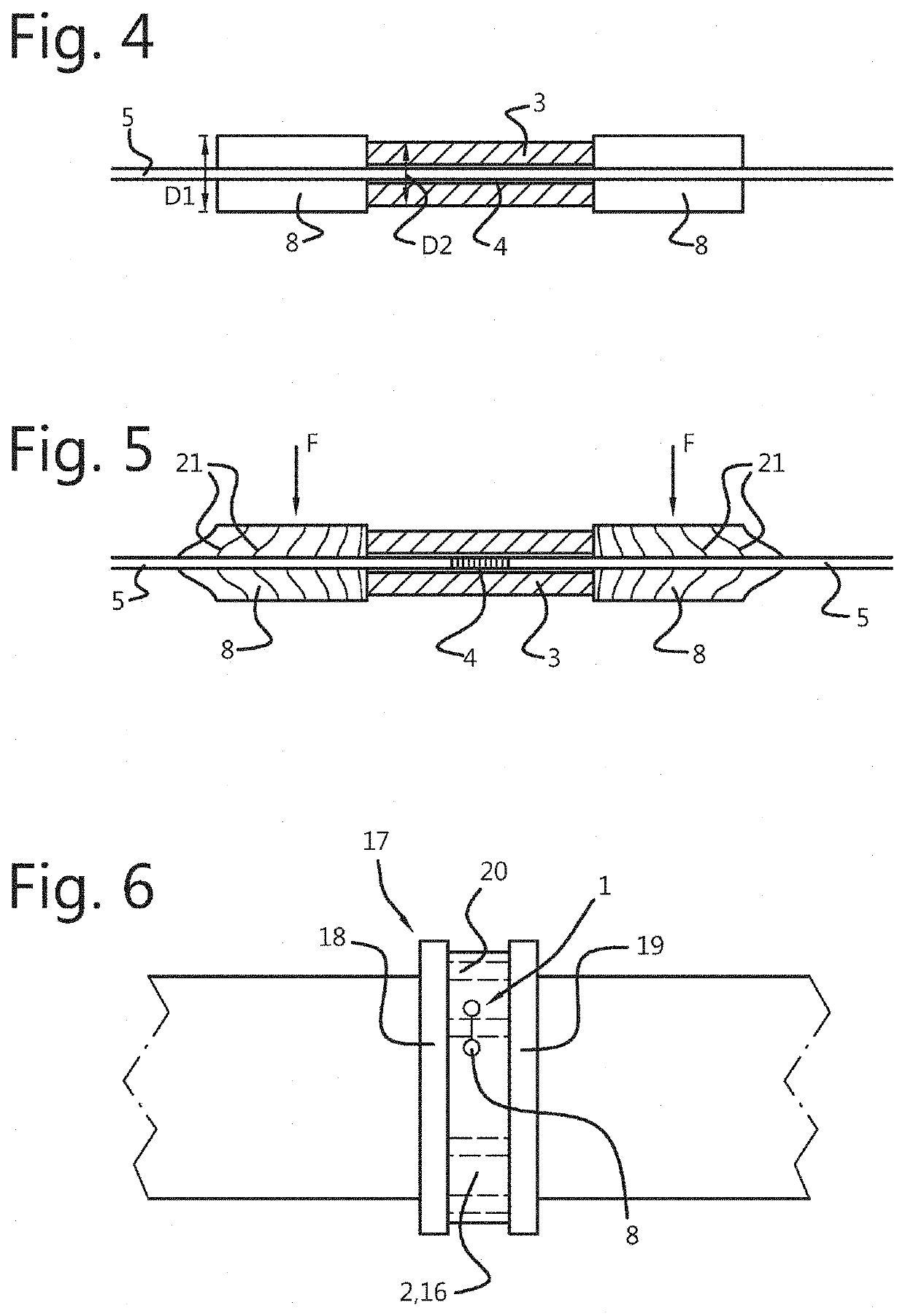
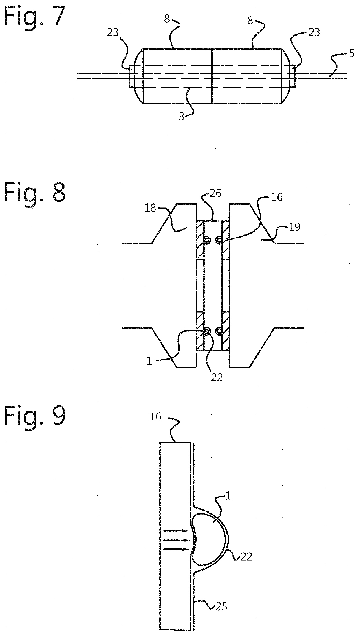
[0009]Hereto, according to the invention, an optical fiber sensing device for sensing the distribution of the compression or deformation of a compressible or deformable element is provided, comprising:

[0010]a substantially incompressible or undeformable tubular element with a recess extending in a length direction of the tubular element, the recess being enclosed by the tubular element,

[0011]an optical fiber arranged in the recess, the optical fiber comprising one or more light distortion structures, such as a fiber Bragg grating, and being expandable in the length direction of the recess,

[0012]one or more expandable elements, having a higher compressibility or deformability than the tubular element in a transverse direction, arranged at one or both ends of the tubular element, the optical fiber being enclosed, such as embedded, in the expandable elements, the expandable elements being arranged for expanding or contracting in the length direction, along with the optical fiber, when ...


PUM

PropertyMeasurementUnit
diameters D2aaaaaaaaaa

Abstract

The invention relates to an optical fiber sensing device (1) for sensing the distribution of the compression/deformation of a compressible/deformable element (2), comprising: an incompressible/undeformable tubular element (3) with a recess (4) extending in a length direction (X) thereof, the recess being enclosed by the tubular element, an optical fiber (5) arranged in the recess, comprising one or more light distortion structures (6), and being expandable in the length direction of the recess, one or more expandable elements (8), having a higher compressibility/deformability than the tubular element in a transverse direction (Y), arranged at one or both ends (9) of the tubular element, the optical fiber being enclosed in the expandable elements, which are arranged for expanding/contracting in the length direction, along with the optical fiber, when the expandable elements are subjected to a transverse load (F).

Description

FIELD OF THE INVENTION[0001]The present invention relates to an optical fiber sensing device for sensing the distribution of the compression or deformation of a compressible or deformable element, an optical fiber sensing system comprising such an optical fiber sensing device, an optical fiber sensing assembly comprising such an optical fiber sensing device or such an optical fiber sensing system, as well as a method for sensing a pressure distribution, preferably for calibrating and sensing a pressure distribution, in a compressible or deformable element, using such an optical fiber sensing assembly.BACKGROUND OF THE INVENTION[0002]Such optical fiber sensing devices are known from the prior art. For instance, U.S. Pat. No. 7,405,818 B2 discloses a seal for preventing leakage of fluid from between a first member and a second member has a seal body and a seal wear indicator. The second member is capable of moving toward and away from the first member. The seal body is adapted for eng...

Claims


Application Information

Patent Timeline
Patent Type & Authority Applications(United States)
IPC IPC(8): G01L1/24
CPCG01L1/246G01D5/35316
Inventor VAN DER HOEK, MARINUS JACOBUS
Owner COMPASS EURO GRP CEG BV
Why Eureka
Try Eureka