Sonar system with increased transverse beam width

a transverse beam and array technology, applied in the field of sonar transducer arrays, can solve the problems of increasing the cost of fabricating arrays on cylindrical contours, inconvenient providing a live side-scan sector image, and small radiating area of arrays, so as to increase the transverse beam width of an acoustic beam, reduce the total radiated power of the beam and reduce the total intensity of the beam.

Active Publication Date: 2021-05-06
NAVICO
View PDF6 Cites 2 Cited by
  • Summary
  • Abstract
  • Description
  • Claims
  • Application Information

AI Technical Summary

Benefits of technology

[0008]For a given acoustic beam, the beam width in the transverse direction depends on the geometry of the transducer elements, and the beam width can be increased by decreasing the length or height of the transducer elements along the transverse direction. However, doing so causes a reduction in the radiated on-axis intensity in the longitudinal direction. In other words, there is a tradeoff between increasing the transverse direction beam width of an acoustic beam and reducing both the total radiated power in the beam and the total intensity of the beam due to geometric spreading. Accordingly, if the transducer element is reduced in length or height in the transverse direction to generate a higher transverse beam width, the result is less acoustic signal energy at the point of the interrogated object. Likewise, due to reciprocity, there is less total force on the receiving transducer elements and less signal energy for a given source located in the field of view of the array.
[0009]It is possible to provide a cylindrical array wherein transducer elements are distributed in two directions on a cylindrical surface (or multiple line arrays distributed azimuthally around the axis of a cylinder) such that the multiple acoustic beams will be deployed and, together, they will define an increased transverse field of view. However, there are a number of drawbacks with this approach. Among other things, it is more expensive to fabricate arrays on a cylindrical contour. Moreover, the radiating areas of the arrays are very small, and the total radiated power will be small.

Problems solved by technology

Some such frequency-steered sonar arrays are not suitable for providing a live sidescan sector image because the beam width in the transverse direction is not wide enough to provide sufficient context from which an operator may identify structures, objects, and the lake or sea bed from the surface.
However, there are a number of drawbacks with this approach.
Among other things, it is more expensive to fabricate arrays on a cylindrical contour.
Moreover, the radiating areas of the arrays are very small, and the total radiated power will be small.

Method used


Image

  • Sonar system with increased transverse beam width
  • Sonar system with increased transverse beam width
  • Sonar system with increased transverse beam width

Examples


example environment

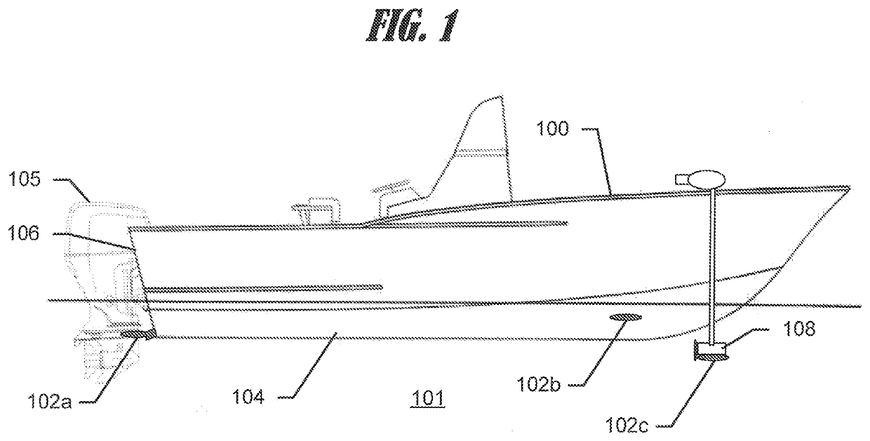
[0048]As depicted in FIG. 1, a watercraft, e.g. vessel 100, configured to traverse a marine environment, e.g. body of water 101, may use one or more sonar transducer assemblies 102a, 102b, and 102c disposed on and / or proximate to the vessel. The vessel 100 may be a surface watercraft, a submersible watercraft, or any other implementation known to those skilled in the art. The transducer assemblies 102a, 102b, and 102c may each include one or more transducer elements configured to transmit sound waves into a body of water, receive sonar return signals from the body of water, and convert the sonar return signals into sonar return data.

[0049]One or more sonar, or acoustic, beams may be generated by the one or more transducer assemblies 102a, 102b, and 102c when deployed in the body of water 101. In some instances, a plurality of transducer elements may be embodied in a transducer assembly. In some instances, the transducer assembly may include one or more of a right scanning (e.g., sid...

example architecture

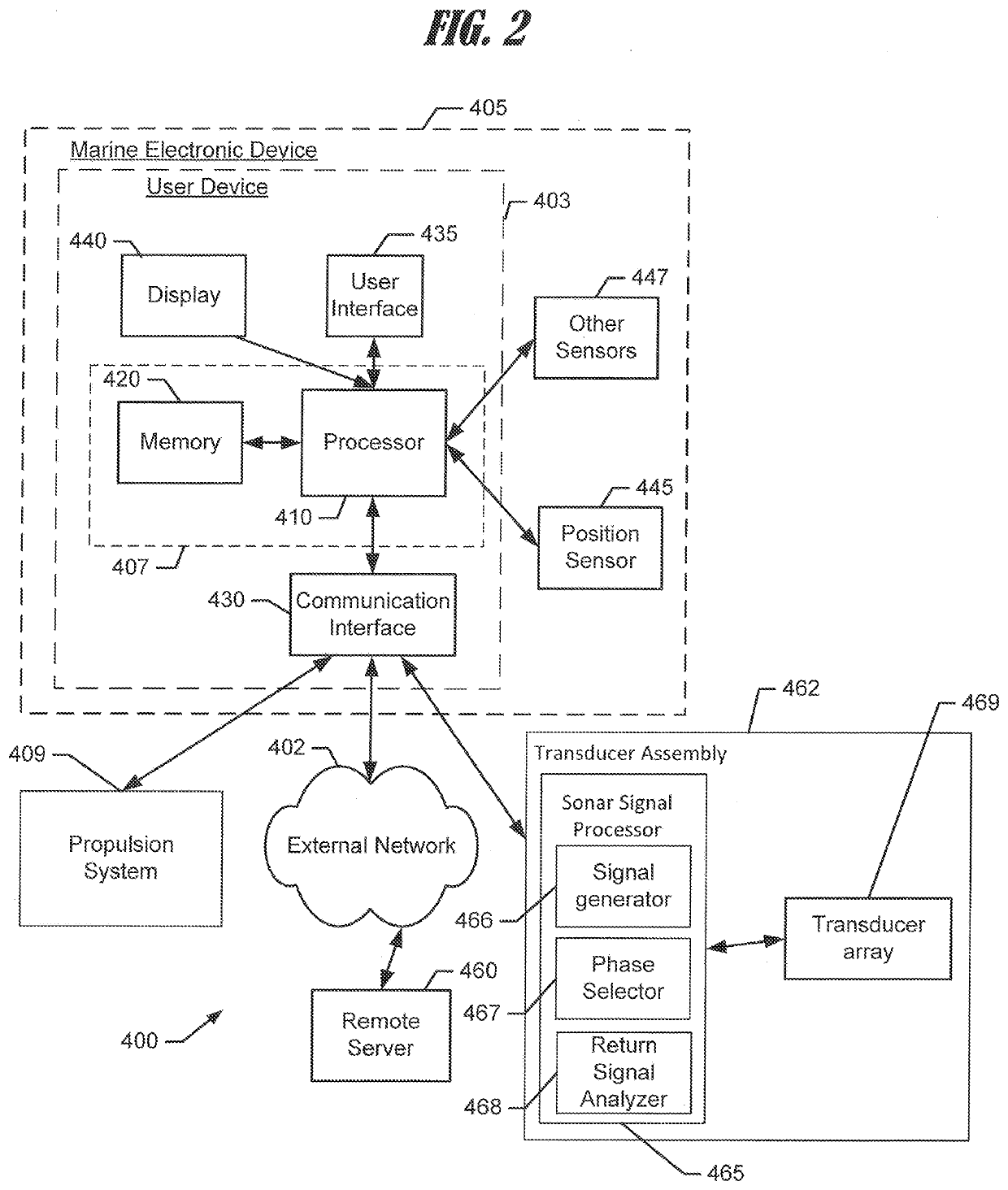
[0056]FIG. 2 shows a block diagram of a computing device, such as user device 403. A depicted computing device is an example marine electronic device 405. The marine electronic device 405 may include a number of different modules or components, each of which may comprise any device or means embodied in either hardware, software, or a combination of hardware and software configured to perform one or more corresponding functions. The marine electronic device may also be in communication with a network 402.

[0057]The marine electronic device 405 may also include one or more communications modules configured to communicate with one another in any of a number of different manners including, for example, via a network. In this regard, the communications module may include any of a number of different communication backbones or frameworks including, for example, Ethernet, the NMEA 2000 framework, GPS, cellular, WiFi, or other suitable networks. The network may also support other data source...

example sonar

Systems

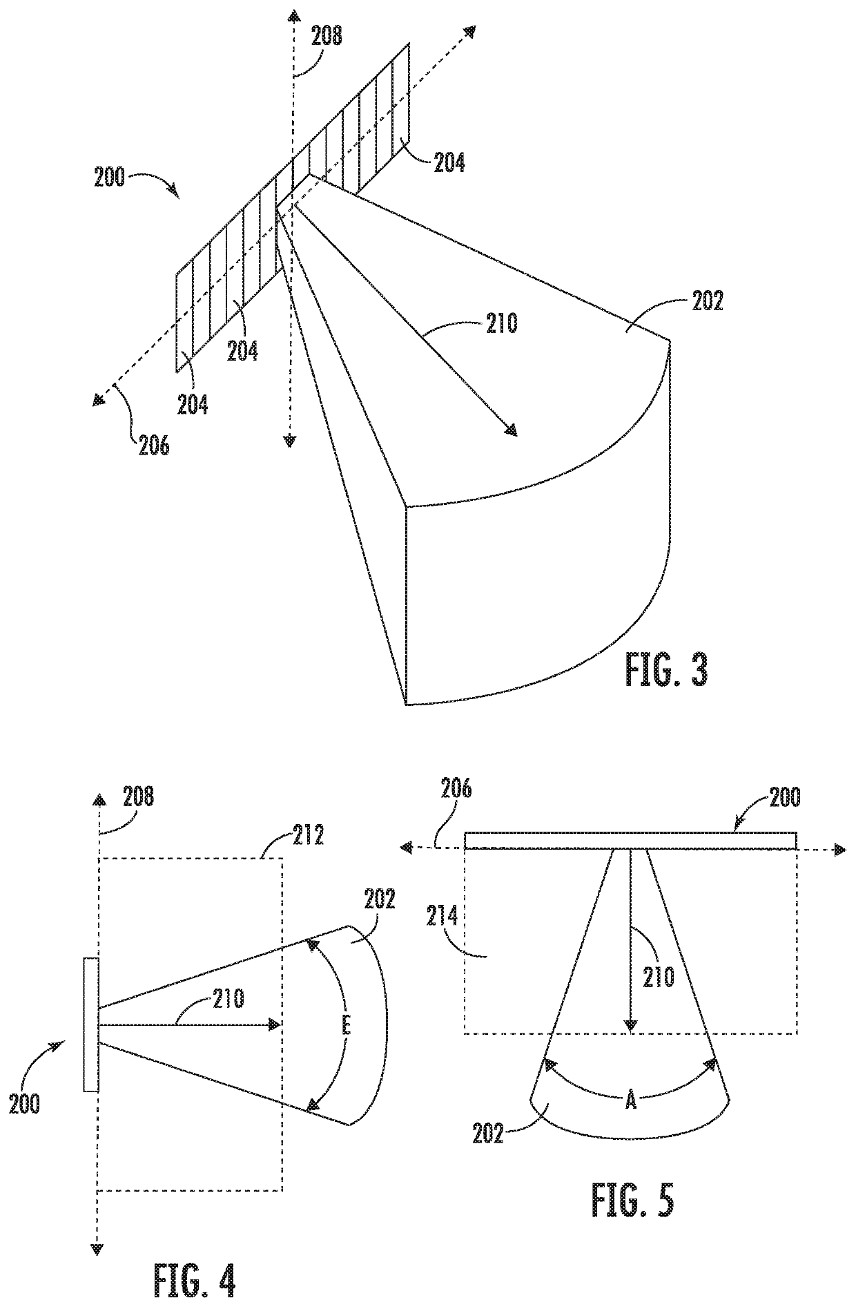
[0075]First, certain aspects of an exemplary configuration and geometry of a transducer array and a resulting acoustic beam are discussed with reference to FIGS. 3-5. These figures present schematic perspective, side, and plan views of a frequency-steered transducer array 200 producing an acoustic beam 202 in accordance with some example embodiments. When used herein, the terms “beam” and “acoustic beam” may refer to a sound wave propagating in a well-defined direction, but they may also refer to a portion of a sound wave pattern wherein the portion propagates along a given direction. Those of skill in the art will appreciate that dispersion of a beam may occur for various reasons, and thus the depictions of acoustic beam 202 in the present disclosure are simplified for the purpose of illustration. Additionally, some example embodiments are described below in the context of sound waves emanating from a transducer array, and thus in FIGS. 3-5 acoustic beam 202 is depicted as p...


PUM


Abstract

Sonar systems and related methods are provided. A sonar system includes a transducer array having a transverse axis and a longitudinal axis disposed perpendicularly thereto. A processor is operative to associate signals with a plurality of transducers in the transducer array so as to form a first acoustic beam, which propagates in a beam first direction and has a first beam width in a first transverse plane. The first transverse plane extends along the beam first direction and contains the transverse axis of the transducer array. A beam spreading device having a curved surface is positioned relative to the transducer array such that the first acoustic beam impinges on the curved surface. Following impingement on the curved surface, the first acoustic beam propagates in a beam second direction and has a second beam width in a second transverse plane. The second beam width is greater than the first beam width.

Description

CROSS-REFERENCE TO RELATED APPLICATION(S)[0001]This application claims priority to U.S. Provisional Application No. 62 / 930,693, filed Nov. 5, 2019, entitled “Sonar System with Increased Transverse Beam Width”; which is incorporated herein by reference in its entirety.FIELD OF THE INVENTION[0002]Embodiments of the present invention relate generally to the operation of sonar transducer arrays, and more particularly, to methods and apparatus for increasing the transverse field angular coverage range in sonar transducer arrays using one or more beam spreading devices.BACKGROUND[0003]Sonar has long been used to detect waterborne or underwater objects. For example, sonar devices may be used to determine depth and bottom topography, detect fish or other waterborne contacts, locate wreckage, etc. In this regard, due to the extreme limits to visibility underwater, sonar is typically the most accurate way for individuals to locate objects underwater. Sonar transducer elements, or simply trans...

Claims


Application Information

Patent Timeline
Patent Type & Authority Applications(United States)
IPC IPC(8): G01S7/521G01S15/89
CPCG01S7/521G01S15/96G01S15/8902G01S15/89G01S15/86G10K11/343G10K11/346G10K11/205G10K11/28G10K11/30
Inventor CASPALL, JAYME
Owner NAVICO
Why Eureka
Try Eureka