
Self-moving educational toy

a toy and self-moving technology, applied in the field of toy self-moving, can solve the problems of not providing mechanical guidance to the vehicle, and achieve the effects of increasing the educational impact of the toy, facilitating production, and keeping maintenance efforts low

Pending Publication Date: 2021-05-06
QUBS AG
View PDF7 Cites 0 Cited by
  • Summary
  • Abstract
  • Description
  • Claims
  • Application Information

AI Technical Summary

Benefits of technology

The patent describes a self-moving vehicle toy that can detect and respond to a marker on the floor. The vehicle has a sensor that reads the marker's machine-readable information and a control unit that uses the information to navigate the vehicle. This allows the vehicle to trigger certain actions based on the marker's features, such as identifying its presence, position, distance, bearing, and other characteristics. The toy also has a memory to store information about previous playruns, including information about the marker read during those runs. This stored information can be used to repeat the playrun without the marker, making it easier to educate children about the toy's programming. Overall, this toy provides a more educational and playful experience for children through its ability to detect and respond to markers on the floor.

Problems solved by technology

This surface can be a preexisting sur face such as a living room floor or a table leaf or it can be provided together with the toy, e.g. in the form of a carpet which can for example comprise certain predefined printed artwork such as buildings and streets, but which does not provide mechanical guidance to the vehicle.

Method used


Image

  • Self-moving educational toy
  • Self-moving educational toy
  • Self-moving educational toy

Examples


first embodiment

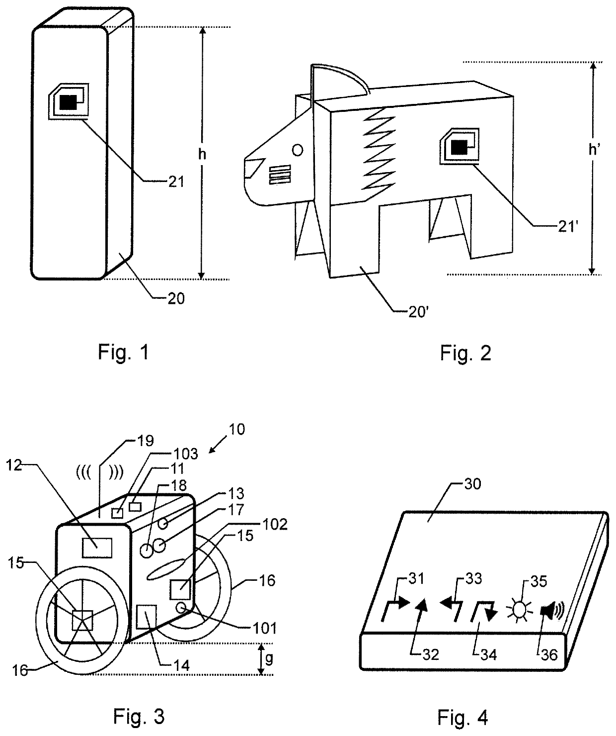
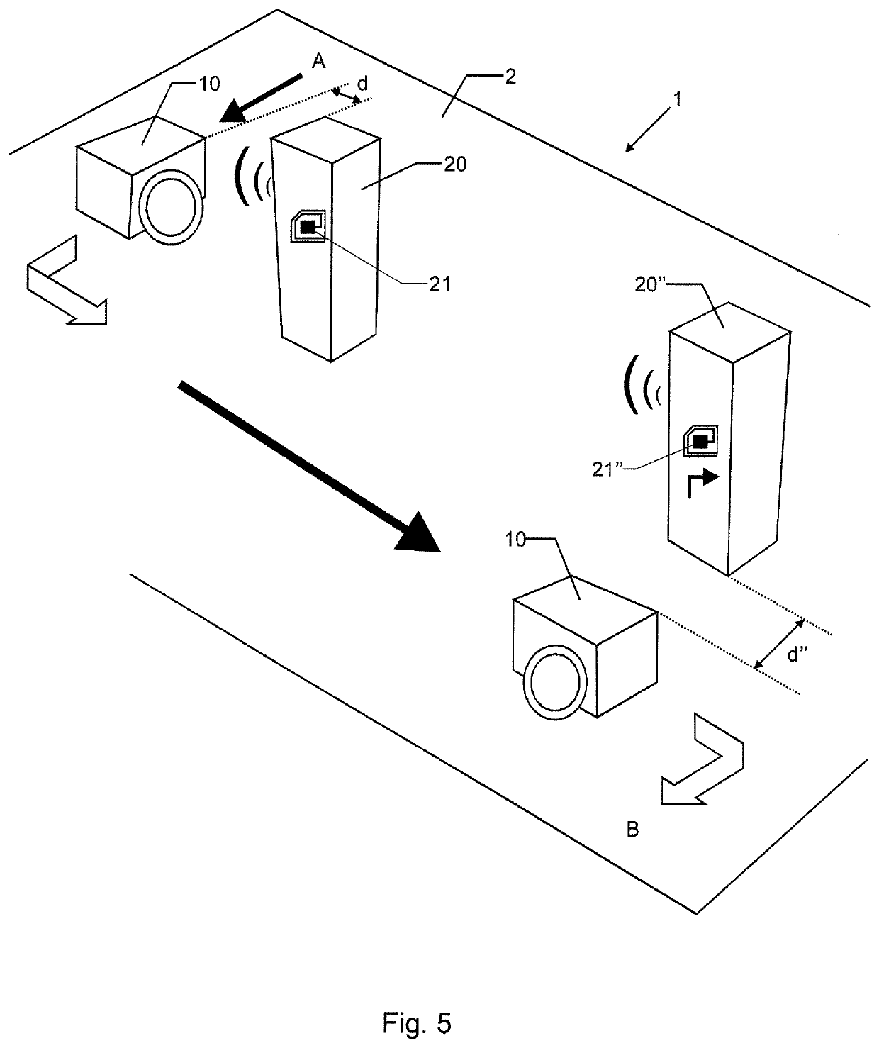
[0070]FIG. 5 shows a perspective view of a toy 1 according to the invention. Here, a first marker 20 as shown in FIG. 1 and a second marker 20′ are placed on a table leaf as surface 2. The second marker 20″ closely resembles the first marker 20 with the exception that an instruction for the first and for the second markers are different such that the markers 20 and 20″ are machine-distinguishable by the vehicle 10. Further, a vehicle 10 as shown in FIG. 3 is placed at a starting point A. Then, the vehicle motion is started, e.g. by pressing a dedicated control button 103 on the vehicle 10. The vehicle 10 then moves in a straight line (standard behavior in the absence of a machine-readable information item 21, 21″, black arrow in the top of the figure), whereby information from the image acquisition device 13 and from the bearing sensor 18 is used by the control unit 12 to control the motors 15 in such a way that the vehicle 10 moves in a straight line. Upon entering a zone around th...

third embodiment

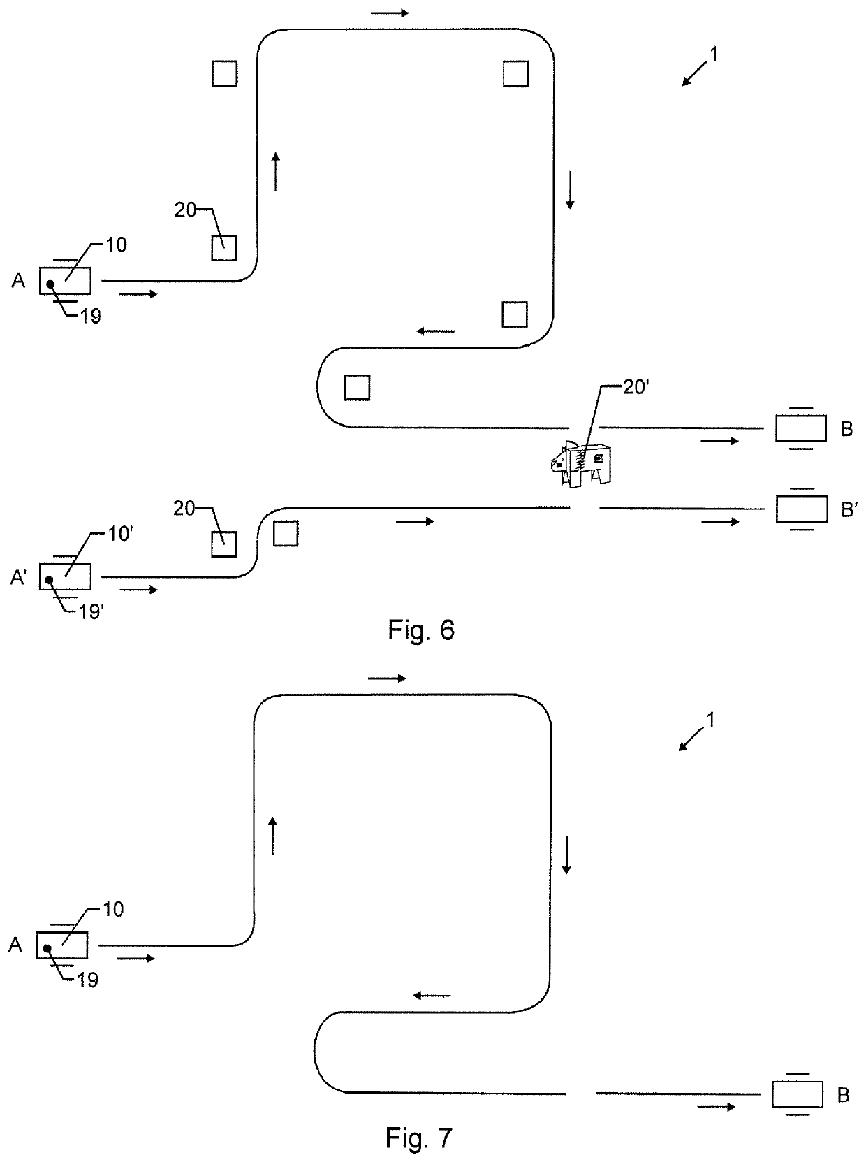
[0079]FIG. 7 shows a top view of a toy 1 according to the invention. In this embodiment, the vehicle 10 as shown in FIG. 6 is, after completing the playrun as described in FIG. 6, brought to the starting point A again and by pressing a control button 103 triggered to re-run the sequence or course as “learned” during the FIG. 6 playrun, but now in the absence of any marker 20, 20′. For this, the vehicle 10 has stored all the required information about the previous FIG. 6 playrun in a memory connected to the control unit 102. Thus, it becomes easier for children to learn about the way, a computer (i.e. the vehicle 10) runs a “program” once it has been “programmed” with an instruction set.

[0080]Using the three-dimensional markers (i.e, the wooden toy blocks and the lion) with machine-readable information items enables the users, e.g. children, to build an instruction sequence by laying out the markers in the desired sequence along a path or course. This provides a powerful visual repre...


PUM


Abstract

An educational toy (1) includes a self-moving vehicle (10) adapted to move and steer freely on a two-dimensional surface (2) such as a table leaf. A tangible, three-dimensional marker (20) includes at least one RFID tag (21) is used to wirelessly trigger a specific action of the vehicle (10), e.g. turn 90 degrees right, when the vehicle (10) enters a readout range of the marker (20). The marker (20) can be placed freely on the surface (2) and cannot be overrun by the vehicle (10). Thus, the vehicle (10) is instructed to perform a certain action, e.g. take a 90 degrees left turn, using the marker (20). Then, the vehicle (10) moves forward until a next marker (20′) is found from which the vehicle (10) receives its next instruction. This enables the educational toy (1) to teach programming during play, which reduces the risk that a user will lose interest.

Description

BACKGROUND OF THE INVENTIONField of the Invention[0001]The present invention relates to a self-moving toy for educational purposes which is controllable by a wireless readout of tangible three-dimensional markers. The toy as well as the markers can be placed freely on a surface.Discussion of Related Art[0002]Robots for educational purposes are known, especially for the purpose of teaching children with no or little experience of programming languages how to program a computer.[0003]EP 3 282 327 A1 discloses such a programmable robot for educational purposes comprising a body and a separate head, which robot scans an area between the wheels of the robot for certain information carrying cards and on navigating over a street of such cards responds with specific actions.[0004]The disclosed device has the disadvantage, however, that the robot cannot move freely on a surface and particularly depends on a closed street of cards for navigation. Thus, its educational impact is limited.SUMMAR...

Claims


Application Information

Patent Timeline
Patent Type & Authority Applications(United States)
IPC IPC(8): G09B19/00A63H17/395G09B1/32G05D1/02
CPCG09B19/0053A63H17/395G09B1/325A63H11/20G05D1/0268G05D1/0287A63H2200/00G05D1/0234A63H33/005G05D2109/10G05D2105/32G05D2111/34G05D1/247
Inventor BULMAN, HAYRI C.
Owner QUBS AG
Learn More