
Ultrasound position-determination system

Active Publication Date: 2021-05-13
SONITOR TECH
View PDF0 Cites 1 Cited by
  • Summary
  • Abstract
  • Description
  • Claims
  • Application Information

AI Technical Summary

Benefits of technology

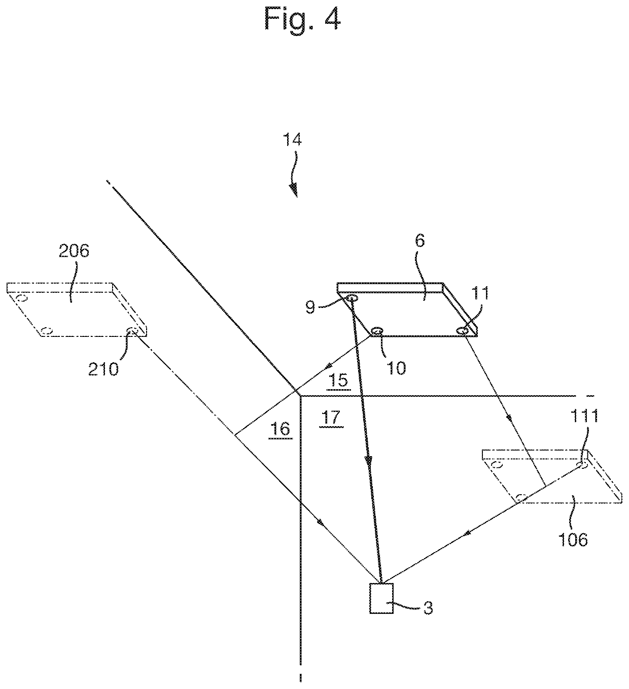
The present invention uses the time of arrival of reflected signals to determine the position of a mobile unit, without being affected by unwelcomed reflections. By exploiting reflections off a surface in the environment, the invention increases positioning accuracy and potentially reduces the number of separate transmitter units needed to provide coverage of a room or area. The system requires fewer static units to be installed, which is cheaper, and cheaper to maintain. The processing system identifies one or more clusters of arrival times for signals encoding different respective direction identifiers which are within a predetermined maximum time-of-flight distance of each other, which increases the likelihood that all the peaks in a cluster relate to signals that have followed the same path to the receiver unit. The technical effects of the invention are improved positioning accuracy and cost-effectiveness.

Problems solved by technology

It therefore requires less accurate time measurements for a given spatial resolution, compared with speed-of-light signals.
This means that a signal can easily be blocked from reaching a mobile unit when the mobile unit is shielded by the human body, or by any other obstruction in the line of sight from a static transmitter unit.
When this happens, reflections off surfaces in the environment may arrive at the mobile unit with greater energy than a direct-path signal and so may be incorrectly identified as direct-path signals, leading to substantial errors in estimating the position of the mobile unit.
Known ultrasound-based positioning systems are also often expensive to install and maintain.

Method used


Image

  • Ultrasound position-determination system
  • Ultrasound position-determination system
  • Ultrasound position-determination system

Examples


Embodiment Construction

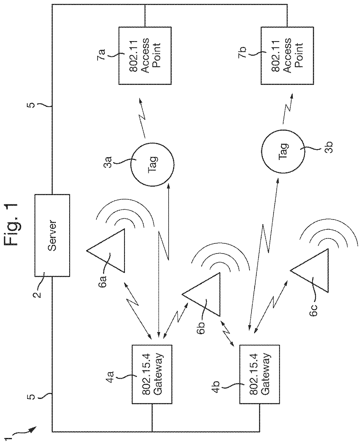
[0092]FIG. 1 shows a three-dimensional positioning system 1 which may be installed in a building, such as a hospital. It enables a server 2 to determine the positions of a number of mobile tags 3a, 3b (mobile receiver units) within the building, to a high level of accuracy, in three dimensions. The tags 3a, 3b are typically attached to a person (e.g., by a lanyard around a person's neck, or with a wrist band), or to an item of equipment, such as a thermometer or a hospital bed. A tag may however be integral with, of formed from, another object, such as being a laptop computer or a mobile telephone. Details of an object associated with a tag may be stored on the server 2. The server 2 also stores a map of the environment, such as a plan of floor and wall locations of a building, in which the tags 3a, 3b are present. It may output textual, graphical, or other data indicating the locations of the tags 3a, 3b, such a visual display of a floor plan with the estimated locations and height...


PUM


Abstract

A system is provided for determining the position of a mobile receiver unit in an environment. The system comprises: a transmission apparatus comprising a plurality of ultrasound transmitters configured to transmit a plurality of ultrasonic signals in different respective principal directions, each encoding a different respective direction identifier; a mobile receiver unit comprising an ultrasound receiver configured to receive the plurality of ultrasonic signals along a plurality of signal paths, at least one of which includes a reflection off an environment surface; and a processing system comprising a decoder arranged to decode the respective direction identifiers from the received signals. The processing system is configured to determine a respective time of arrival for each signal, and use location information relating to the transmission apparatus and the environment surface, together with the respective direction identifiers and times of arrival to calculate an estimated position of the mobile receiver unit.

Description

BACKGROUNDField[0001]This invention relates to systems and methods for determining the position of a mobile unit using ultrasound signals.Background Information[0002]It is known to use ultrasound to determine the position of a mobile unit, or tag, in three dimension by transmitting ultrasonic signals from a plurality of static transmitter units at known positions in the environment (e.g., on the walls or ceilings of a building). These signals are received by the mobile receiver unit, which may be attached to an object. Given the positions of the static transmitter units, the times of arrival of the ultrasonic signals at the mobile unit can be used to estimate the position of the mobile unit in the environment, using standard geometric calculations. An example of such a system is described in U.S. Pat. No. 6,292,106 (Cubic Defence Systems, Inc.).[0003]Ultrasound is well suited to use in positioning systems, especially indoors, as it travels much slower than radio waves and light. It ...

Claims


Application Information

Patent Timeline
IPC IPC(8): G01S5/30
CPCG01S5/30G01S5/18
Inventor BOOIJ, WILFRED EDWINANTILLE, CYRILOLSEN, ØYSTEIN HAUG
Owner SONITOR TECH
Learn More