
Supported spindle and manufacturing method for a supported spindle

a technology of supported spindles and manufacturing methods, which is applied in the direction of braking systems, vehicle sub-unit features, gearing, etc., can solve the problem of lengthening the service life of the particular supported spindl

Active Publication Date: 2021-06-03
ROBERT BOSCH GMBH
View PDF0 Cites 0 Cited by
  • Summary
  • Abstract
  • Description
  • Claims
  • Application Information

AI Technical Summary

Benefits of technology

The present invention provides supported spindles with improved operational stability compared to related art. The support plate and spindle body can be made with relatively minor thicknesses, and the cost-effective manufacturing process ensures sufficient formability. The ring element clamped between the support plate and spindle body ensures bending resistance torque and protects the weld seam from deformation and lateral forces, thus increasing the service life of the spindle. The ring element also prevents welding beads from contaminating the spindle body thread during laser welding. The ring element has at least one material receptacle depression and / or at least one relief groove to ensure a full fit of contact surfaces and prevent cracks. The load path for an axial load is guided through the ring element. The weld seam has an average width radially in relation to the center longitudinal axis of the spindle body, and an air gap is provided between the section of the spindle body framed by the ring element to prevent welding-on of the ring element.

Problems solved by technology

This lengthens a service life of the particular supported spindle.

Method used


Image

  • Supported spindle and manufacturing method for a supported spindle
  • Supported spindle and manufacturing method for a supported spindle
  • Supported spindle and manufacturing method for a supported spindle

Examples


Embodiment Construction

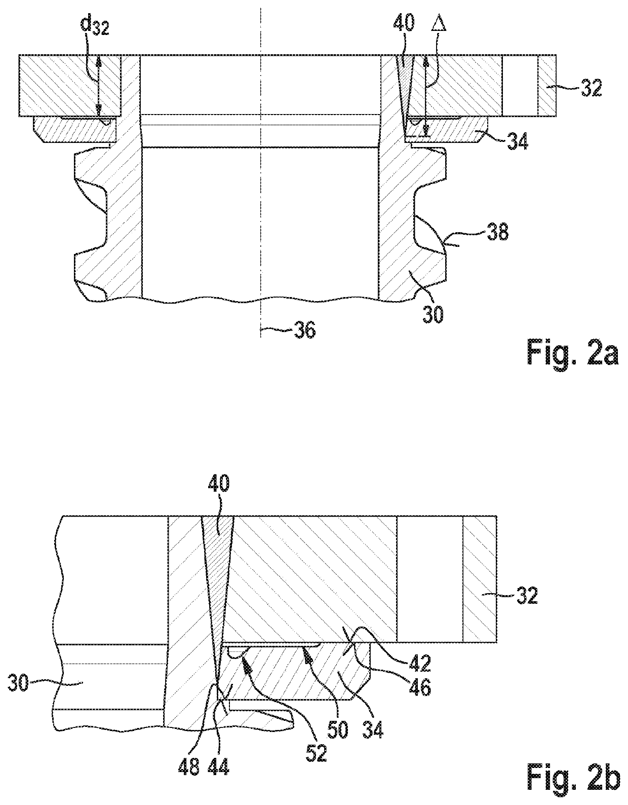
[0025]FIGS. 2a and 2b show schematic overall and partial representations of a first specific embodiment of the supported spindle in accordance with the present invention.

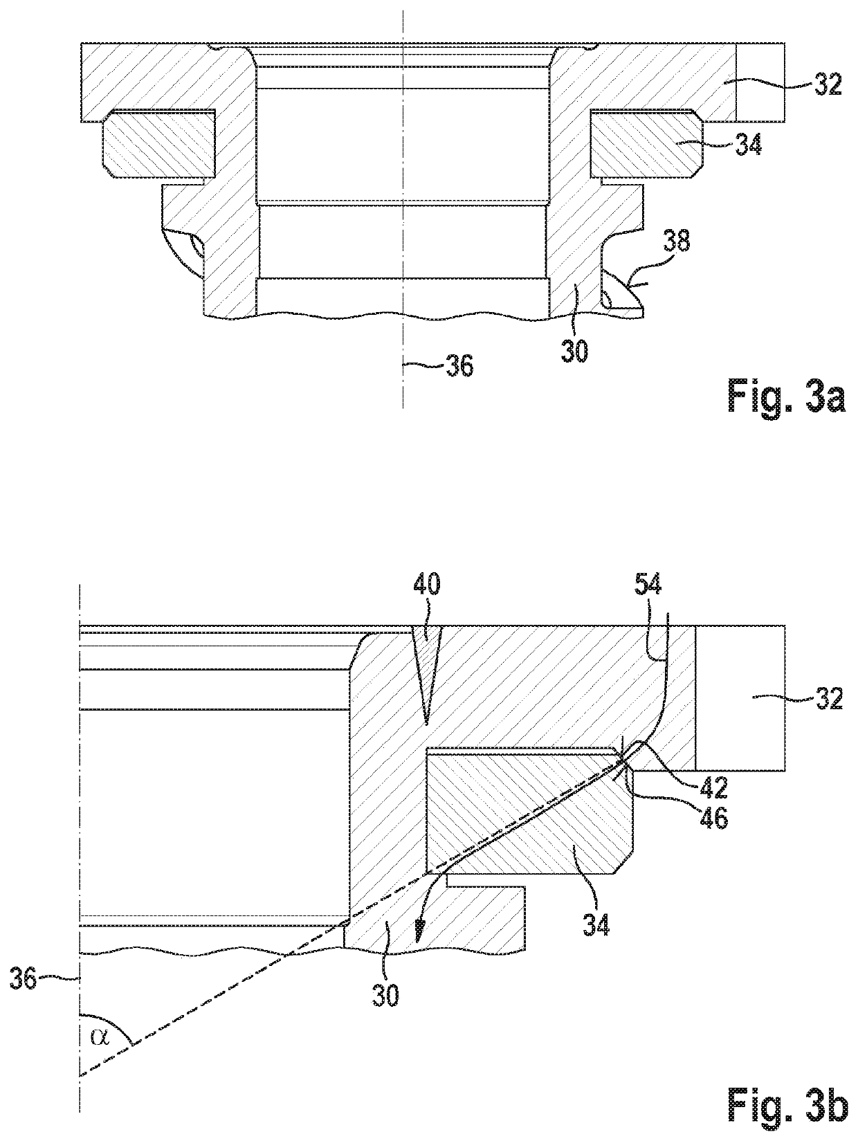
[0026]The supported spindle schematically shown in FIGS. 2a and 2b includes a spindle body 30, a support plate 32, and a ring element 34. The supported spindle formed from (at least) components 30 through 34 may thus also be referred to as a supported spindle component.

[0027]The supported spindle formed from (at least) components 30 through 34 is designed to cooperate with a spindle nut (not shown). The supported spindle is installable for this purpose in and / or at a device equipped with the spindle nut. Spindle body 30 extending along its center longitudinal axis 36 includes a spindle body thread 38 (as a male thread), which extends “spiraled” around center longitudinal axis 36 of spindle body 30 and with which a spindle nut thread of the spindle nut may engage.

[0028]Support plate 32 is to be understood as a compon...


PUM


Abstract

A supported spindle for a device equipped with a spindle nut. The supported spindle includes a spindle body extending along its center longitudinal axis, a support plate, which is welded onto the spindle body in such a way that a weld seam formed between the spindle body and the support plate extends around the center longitudinal axis of the spindle body, and a ring element framing a section of the center longitudinal axis of the spindle body, which contacts the support plate on at least one first contact surface of the ring element and contacts the spindle body on at least one second contact surface of the ring element in such a way that the ring element is clamped between the support plate and the spindle body.

Description

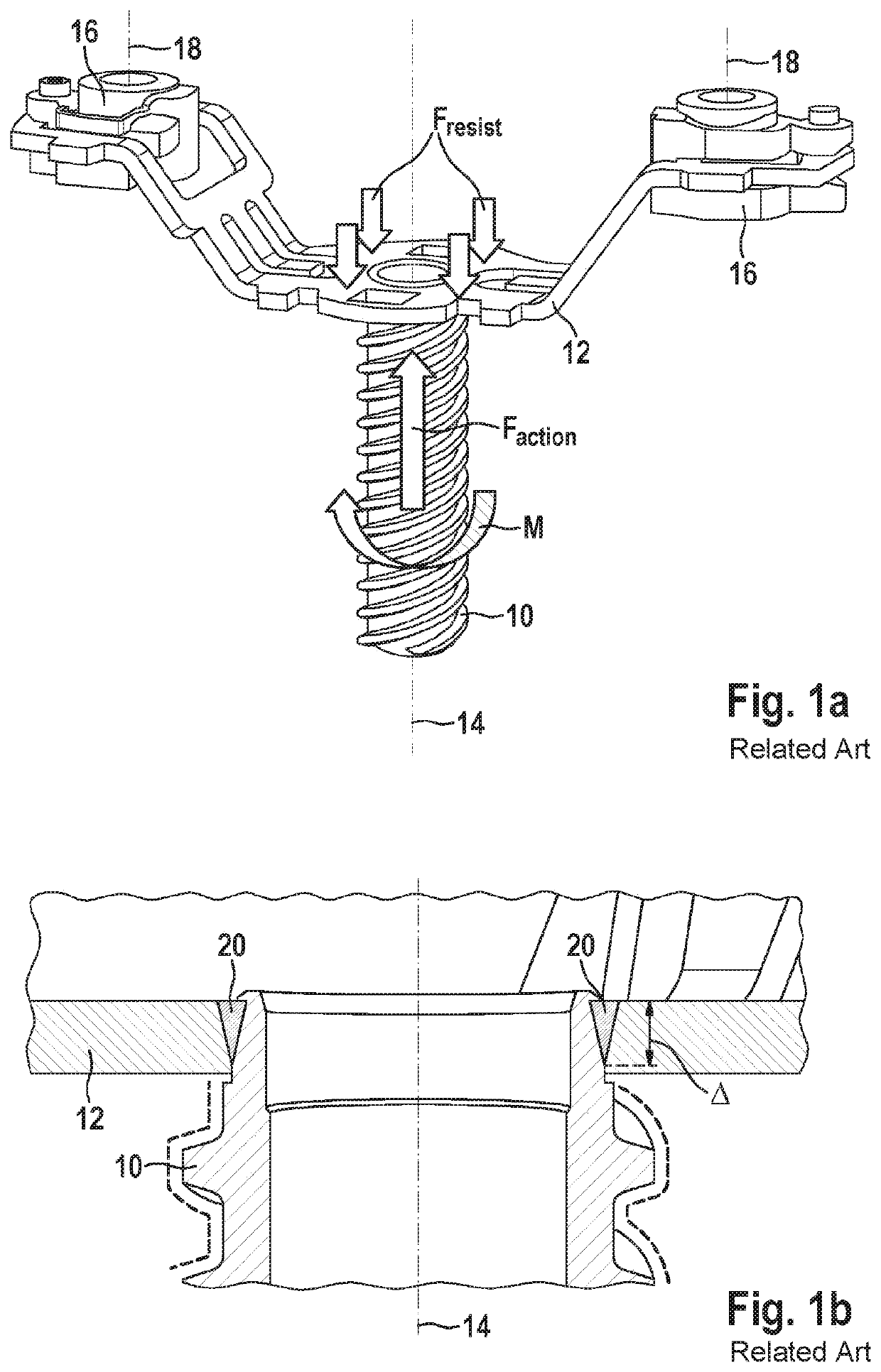
FIELD[0001]The present invention relates to a supported spindle for a device equipped with a spindle nut. The present invention also relates to a device including a supported spindle and a cooperating spindle nut. Furthermore, the present invention relates to a manufacturing method for a supported spindle for a device equipped with a spindle nut.BACKGROUND INFORMATION[0002]FIGS. 1a and 1b show schematic overall and partial representations of a conventional spindle as described, for example, in German Patent Application No. DE 10 2015 217 522 A1.[0003]Conventional spindle 10 which is schematically shown FIGS. 1a and 1b is designed to cooperate with a spindle nut (not shown). In addition, a support plate 12 is welded onto conventional spindle 10, with the aid of which spindle 10 is held in a rotationally-fixed manner. This is to be understood to mean that in the event of a rotation of the spindle nut triggered with the aid of an electric motor (not shown), conventional spindle 10 is a...

Claims


Application Information

Patent Timeline
IPC IPC(8): F16H25/24B60T13/74
CPCF16H25/24F16H2025/2037B60T13/745B60Y2410/124F16H25/20B60T13/143B60Y2400/81F16C3/023
Inventor SCHUETZ, HENNINGNAGEL, WILLI
Owner ROBERT BOSCH GMBH
Learn More