
Display panel and display apparatus using same

a display panel and display panel technology, applied in non-linear optics, instruments, optics, etc., can solve the problems of consuming power, affecting the aperture ratio, and not being environmentally friendly, and achieve the effect of improving the aperture ratio and the display effect of the display panel

Inactive Publication Date: 2021-06-03
HKC CORP LTD
View PDF0 Cites 0 Cited by
  • Summary
  • Abstract
  • Description
  • Claims
  • Application Information

AI Technical Summary

Benefits of technology

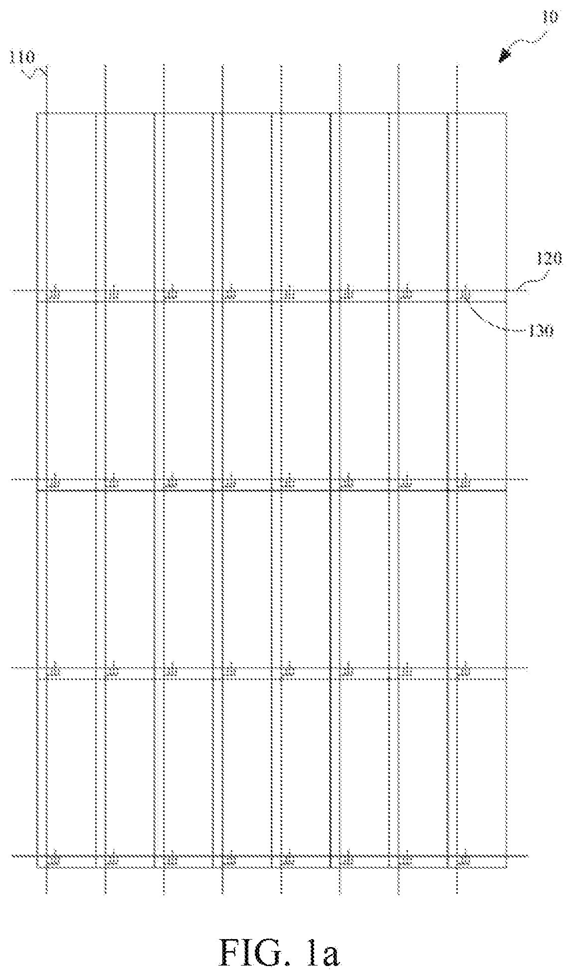
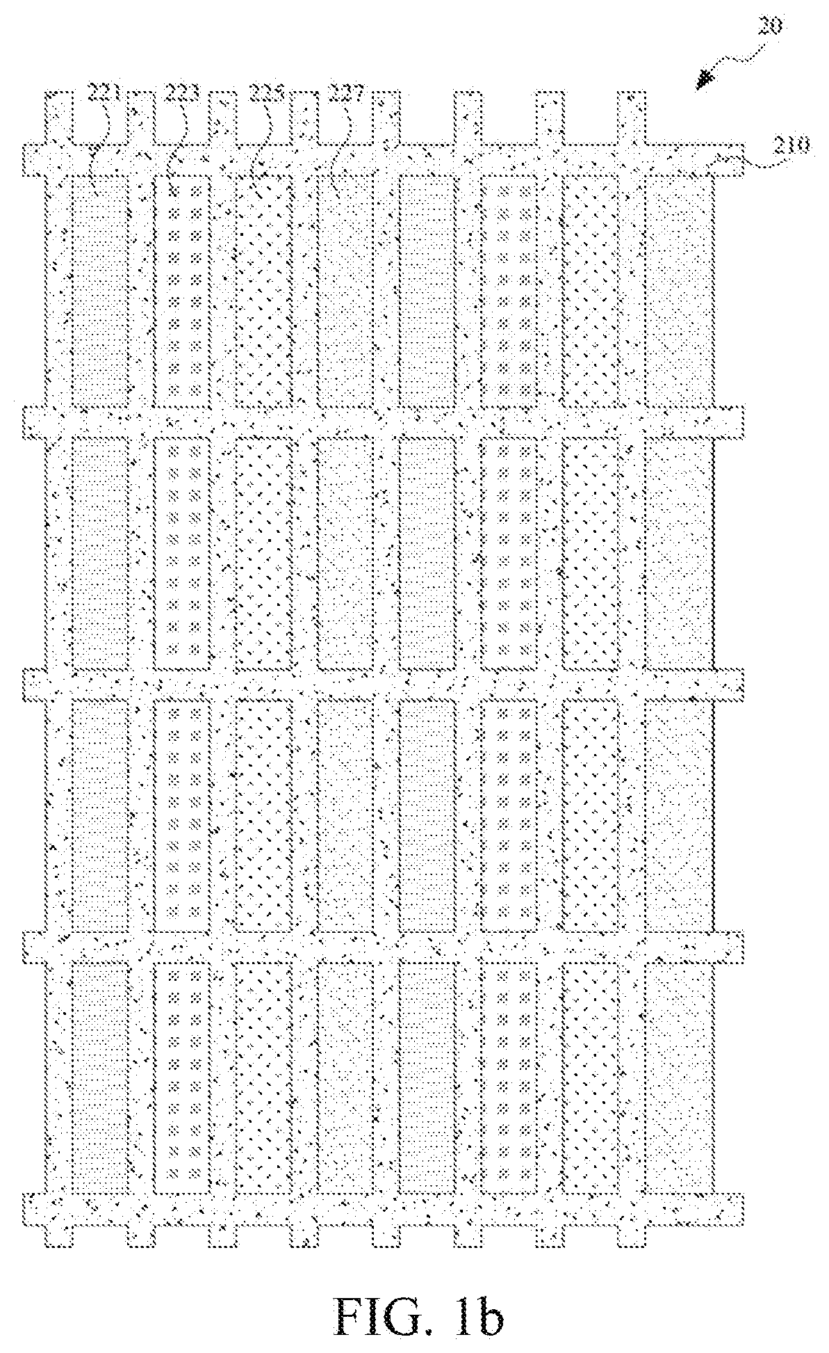
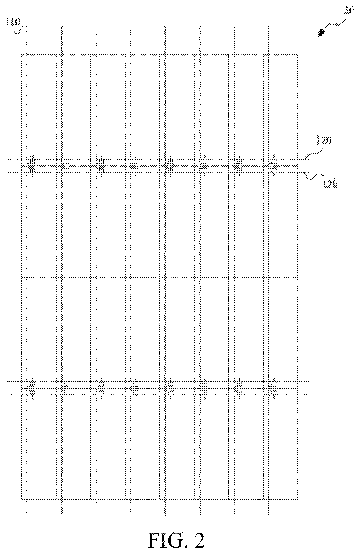
This patent aims to provide a display panel with improved aperture ratio and display effect by reducing the area ratio of the black matrix layer to the display panel through the configuration of data lines and scanning lines, as well as an arrangement design of color filter units.

Problems solved by technology

However, when the light shielding layer is used to shield light, the aperture ratio is affected.
This consumes power and is not environmentally friendly.

Method used


Image

  • Display panel and display apparatus using same
  • Display panel and display apparatus using same
  • Display panel and display apparatus using same

Examples


Embodiment Construction

[0037]The following embodiments are described with reference to the accompanying drawings, which are used to exemplify specific embodiments for implementation of this application. Direction terms mentioned in this application, such as “on”, “below”, “front”, “back”, “left”, “right”, “in”, “out”, and “side” merely refer to directions in the accompanying drawings. Therefore, the direction terms used are for the purpose of describing and understanding this application, and are not intended to limit this application.

[0038]The accompanying drawings and the description are considered to be essentially exemplary, rather than limitative. In the figures, units with similar structures are represented by using the same reference number. In addition, for understanding and ease of description, the size and the thickness of each component shown in the accompanying drawings are arbitrarily shown, but this application is not limited thereto.

[0039]In the accompanying drawings, for clarity, thickness...


PUM

PropertyMeasurementUnit
conductiveaaaaaaaaaa
colorsaaaaaaaaaa
distanceaaaaaaaaaa

Abstract

This application provides a display panel, includes: a first substrate and a second substrate disposed opposite to each other; a active switches, disposed on the first substrate; a conductive lines, disposed on the first substrate, where a (2n−1)th conductive line is disposed adjacent to a 2nth conductive line, the 2nth conductive line is disposed away from a (2n+1)th conductive line; a color filter layer, including a pixel groups disposed on the first or second substrate, where each pixel group includes a adjacent color filter units having different colors; and a light shielding layer, disposed between the color filter units, where the light-shielding layer separates the color filter units; adjacent color filter units of adjacent pixel groups have a same color; and a distance between the 2nth conductive line and the (2n+1)t conductive line is longer than a distance between the (2n−1)th conductive line and the 2nth conductive line.

Description

BACKGROUNDTechnical Field[0001]This application relates to the display field, and in particular, to a display panel and a display apparatus using same.Related Art[0002]Liquid crystal display apparatuses have many advantages such as thin structure, power saving, and no radiation, and are widely applied in recent years. Most of liquid crystal display apparatuses in the existing market are backlit liquid crystal display apparatuses including liquid crystal panels and backlight modules. The working principle of the liquid crystal panel is: Liquid crystal molecules are placed between two parallel glass substrates, and a drive voltage is applied to the two glass substrates to control a rotation direction of the liquid crystal molecules, so as to refract light from the backlight module to produce an image.[0003]Currently, active switch type liquid crystal display apparatuses (Thin Film Transistor-Liquid Crystal Display, TFT-LCD) have gradually occupied a leading position in the display fie...

Claims


Application Information

Patent Timeline
Patent Type & Authority Applications(United States)
IPC IPC(8): G02F1/1362G02F1/1368
CPCG02F1/136286G02F1/1368G02F1/136222G02F1/136209G02F1/133514G02F1/133512G02F2201/40
Inventor HUANG, BEIZHOU
Owner HKC CORP LTD
Learn More